Profile joint
In the following steps, the crane girder of the EHB-I is pre-installed on the ground.
|
Profile joint |
|
|
|
|
The figures show the installation of an HB profile rail of size HB150S. The installation of larger or smaller HB profile rails does not differ significantly from this. |
 The profile rail sections
must be laid out on the building floor the way they are to be later installed.
The profile rail sections
must be laid out on the building floor the way they are to be later installed.
|
|
The position of the profile rail sections is specified in the planning documents. |
The specified dimensions, positions and clearances must be followed exactly.
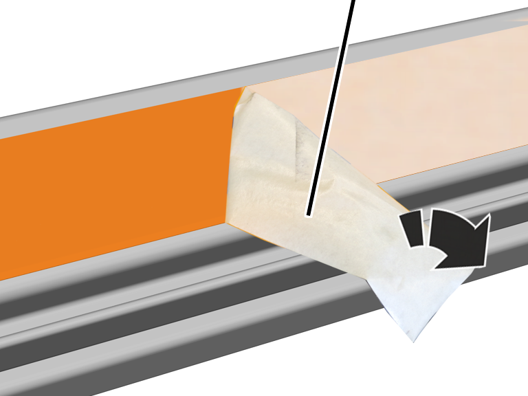
The profile rail sections are laminated at the sides. The protective film is removed before further assembly.
|
|
Protective film |
|
| |
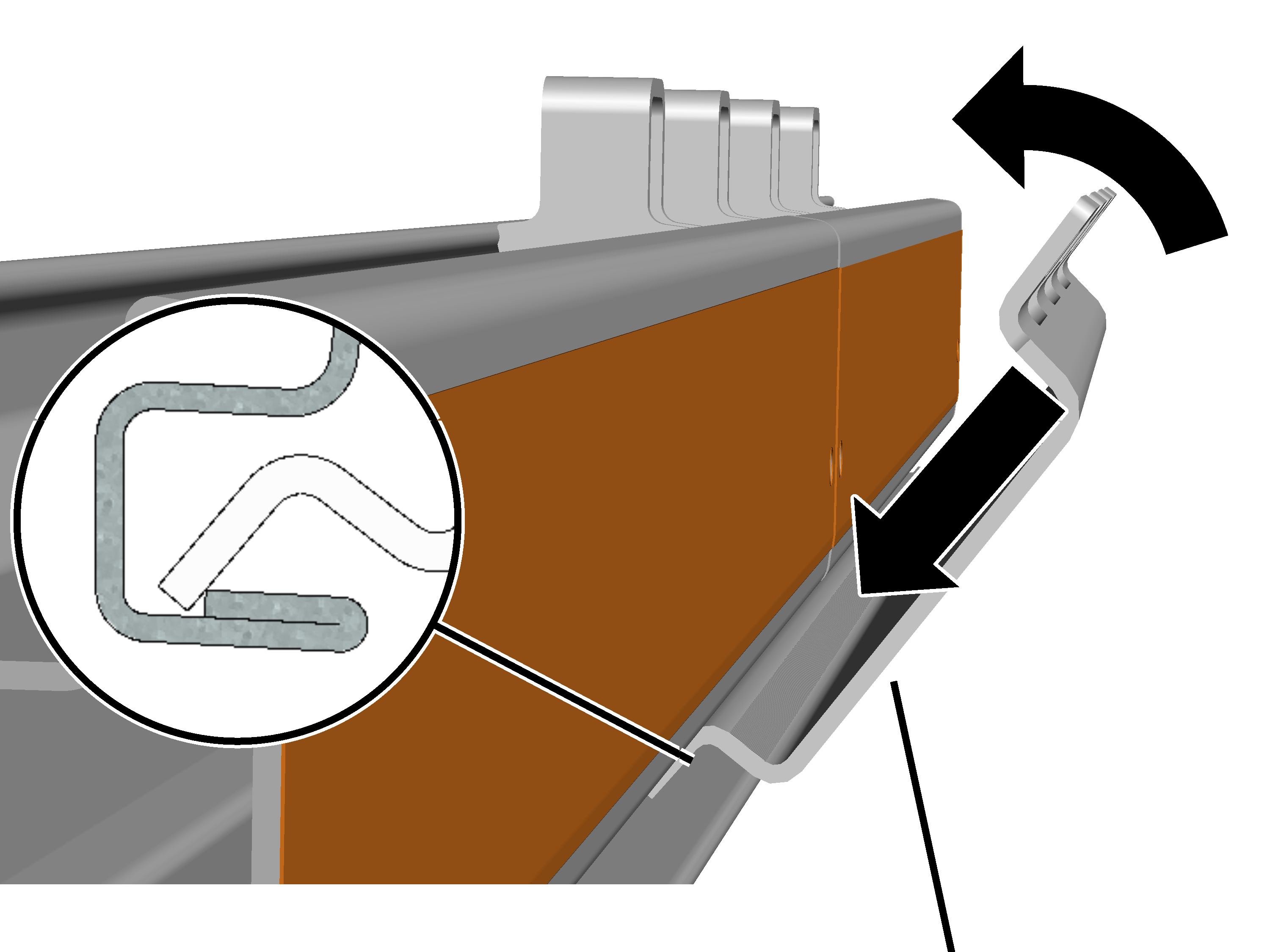
Pull off the protective
film at a sharp angle from the side lamination.
At each profile joint:
|
| |
|
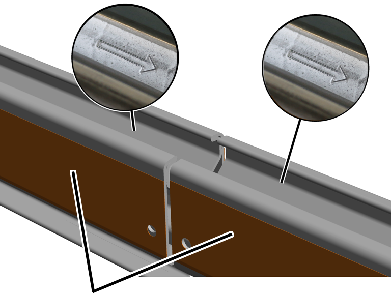
Profile rail sections |
|
Turn the profile rail
sections so that the arrows on all of them point in the same direction.
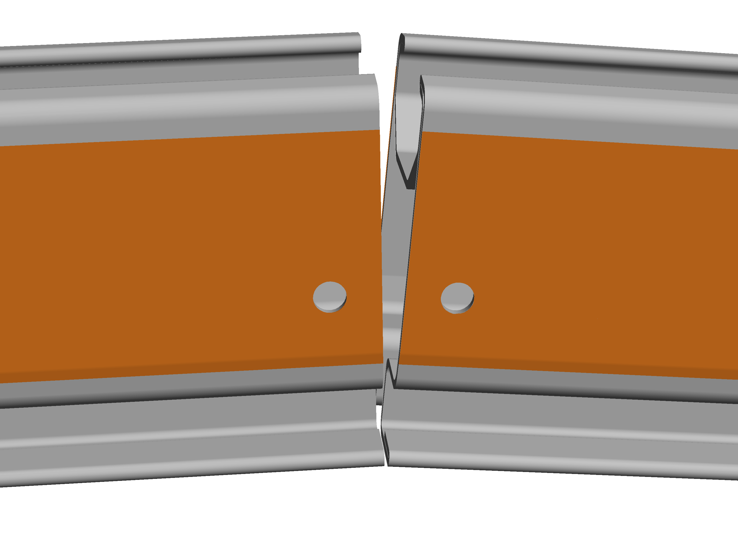
Place the profile rail
sections flush to one another.
|
|
Raise the profile rail
sections just in front of the profile joint by about 5 cm (e.g. on the
floor with a wooden beam or, with suspended assembly, by slightly lowering the
unassembled profile rail section).
● In this way, the profile rail sections join at a slight angle to one another. This ensures that despite the camber (the profile rail sections are arched upward slightly) the distance at the bottom between the profile rails is as small as possible.
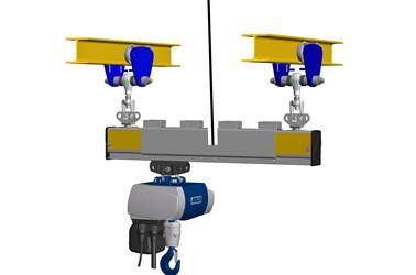
This work step only applies if a crane girder suspension is intended in the area of the clamping plates on a profile joint.
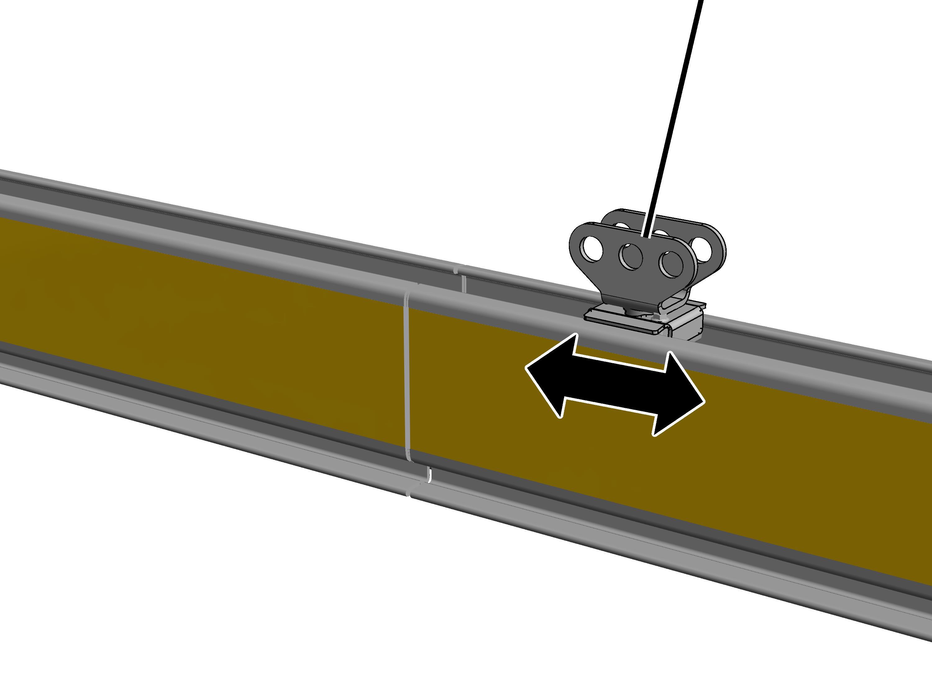
The crane girder suspension can also be installed in the area of a profile joint. To do this, the profile connection must first be pushed precisely to the position at which it will later be screwed tight.
|
|
Profile connection |
|
| |
Push the profile
connection to its intended position.
Once the clamping plate has been installed in the next step, the profile connection can no longer be shifted.
|
| |
|
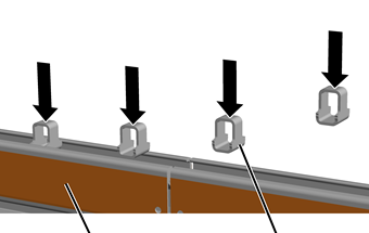
Profile rail section |
Spacer part |
Insert spacer parts from
above in the left and right profile rail sections and, if necessary, knock them
slightly into place.
● The spacer parts are clamped in the profile head but can still slide back and forth.
|
| |
|
|
Clamping plate |
 Tilt the clamping plate
slightly and insert it below in the profile rail section.
Tilt the clamping plate
slightly and insert it below in the profile rail section.
When doing this, insert the bottom of the clamping plate behind the edge on the profile rail section.
Position the clamping
plate so that it is exactly centred between the two profile rail sections.
Press the top of the
clamping plate against the profile rail section.
This work step only applies if a crane girder suspension is intended in the area of the clamping plates on a profile joint.
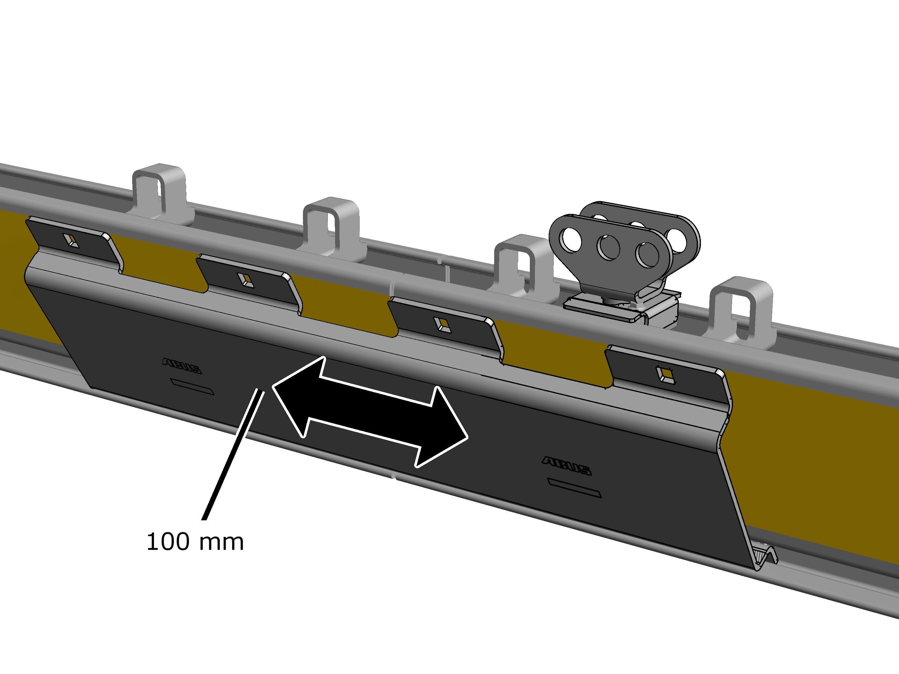
Only with a crane girder suspension in the area of a profile joint: The clamping plates do not need to be inserted exactly centred on the profile joint. The clamping plates may be shifted up to 100 mm to the left or right so that the crane girder suspension can lie at the exactly desired position.
Note:
For a profile joint without a crane girder suspension, the clamping plates must be installed exactly centred!
|
|
Only with a crane girder
suspension in the area of a profile joint: The clamping plates can be shifted up
to 100 mm.
An assembly aid can now be bolted on at the top. It will make it easier to screw the clamping plates together.
On the clamping plate:
|
| |
|
Assembly aid |
Rib nut M12 |
Bolt the assembly aid on
the outer lug with an M12 rib nut.
● The clamping plate is held by the assembly aid and can no longer fall down.
Insert the second clamping
plate as described above on the opposite side and secure it with the assembly
aid.
The assembly screw (which is longer than the actual screws) is used to pull the clamping plates to the HB profile rail so that the actual screws can be inserted.
Check the spacing of the
profile rail sections again.
The profile rail sections can be directly flush to one another. The must not be more than 2 mm apart.
|
Assembly aids |
|
|
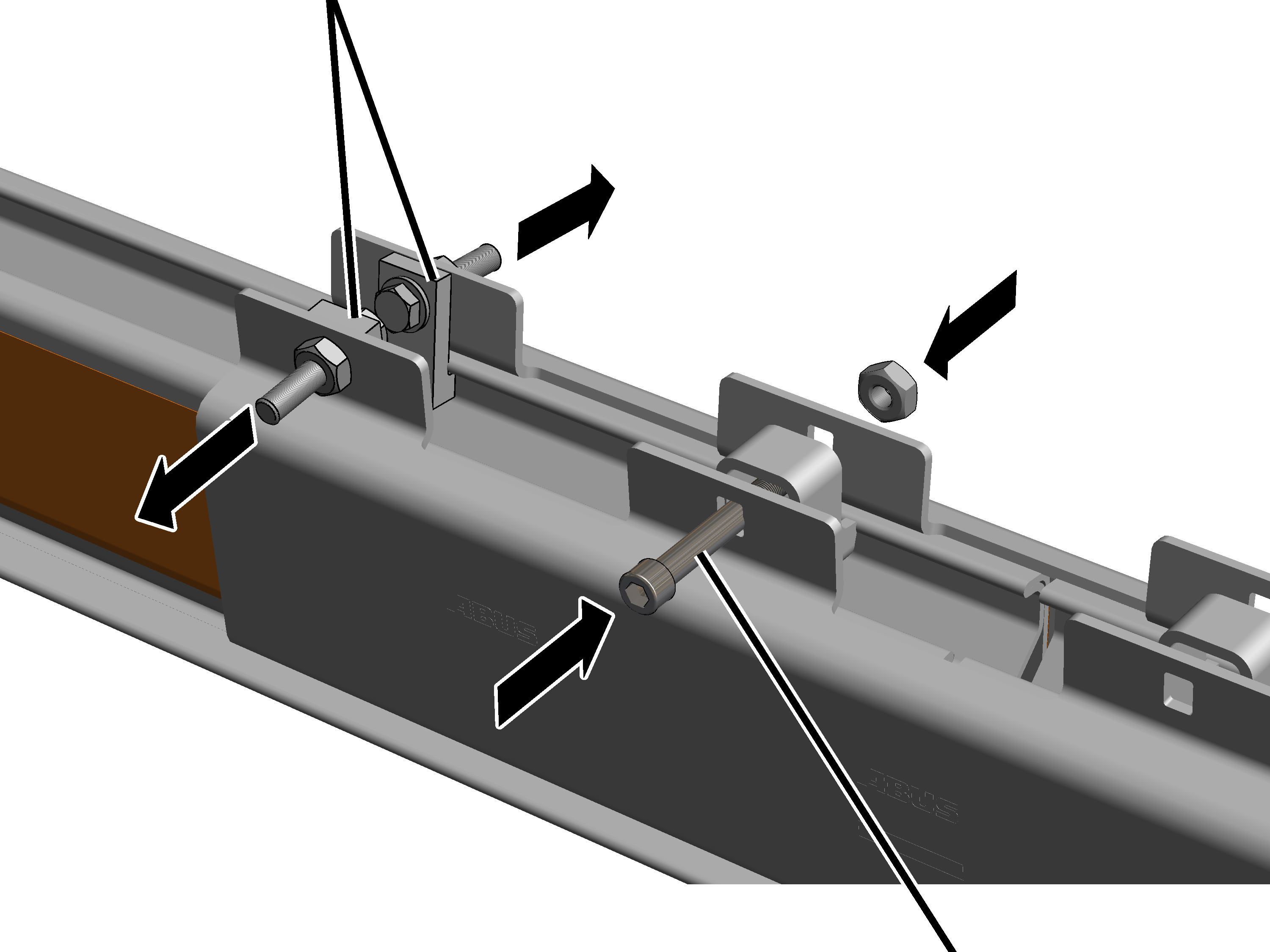
| |
|
|
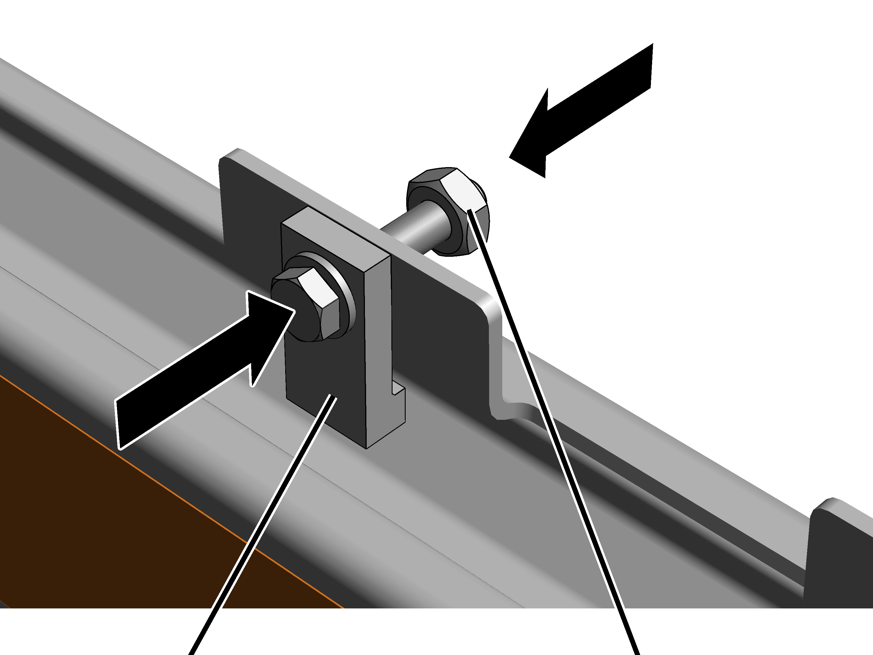
Assembly screw M12x95 |
Insert the M12x95 assembly
screw through two opposite-lying brackets of the clamping plate.
Screw a hexagonal nut onto
the assembly screw.
Continue screwing the
assembly screw and hexagonal nut together to pull the clamping plates to the HB
profile rail from both sides.
Once the assembly screw is
screwed on: remove the assembly aids (2x).
On all spacer parts:
|
Assembly screw |
Hexagonal nut |
|
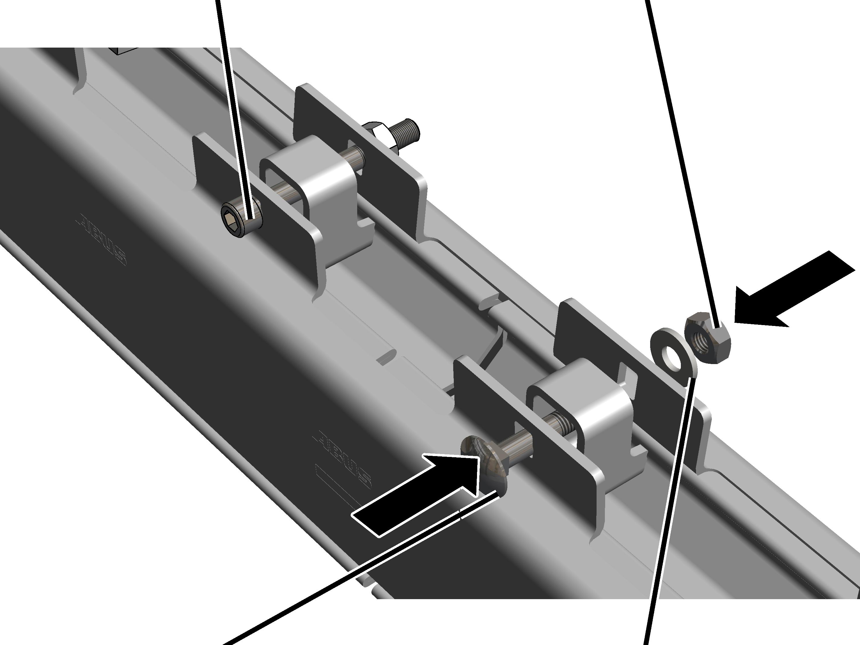
| |
|
Cup square bolt |
Spring washer |
Push the cup square bolts
through the clamping plates and the spacer parts.
|
Size |
Cup square bolt |
Rating |
|
HB150 |
M12x60 |
12.9 |
|
HB190 |
M12x60 |
12.9 |
|
HB240 |
M12x60 |
12.9 |
● The square end of the cup square bolt locks in the clamping plate and therefore cannot turn.
Insert spring washer.
Loosely screw the M12
hexagonal nut onto the cup square bolt.
Screw the hexagonal nuts
on. 120 Nm.
The U-shaped plates included do not have to be installed yet. They are only required if the travel gap is too wide.
After the assembly of the clamping plates, check whether the profile rail sections have bent apart.
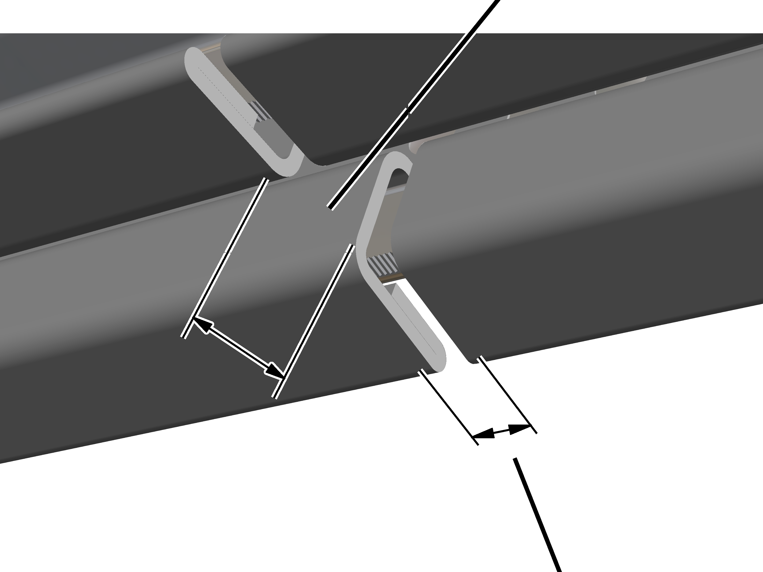
|
|
Travel gap | |
|
| ||
|
|
Distance | |
Check the travel gap in the area of the profile
joint:
─ The travel gap is permitted to be maximally 25 mm wide.
─ The travel gap must be at least 19 mm wide.
If the travel gap is too
wide or too narrow: press the profile rail section together with a screw clamp
or use a suitable lever to press it apart.
Check the spacing of the
profile rail sections.
The profile rail sections can be directly flush to one another. The must not be more than 2 mm apart.
This work step only applies if a crane girder suspension is intended in the area of the clamping plates on a profile joint.
Screw in the rib screws of
the profile connection on the clamping plate (2x).
|
Size |
Rib screw |
Tightening torque |
|
HB150 |
M6x40 |
20 Nm |
|
HB190 |
M6x40 |
20 Nm |
|
HB240 |
M6x40 |
20 Nm |
If the travel gap is still wider than 25 mm:
The enclosed U-shaped plates can be inserted in addition to the spacer parts to reduce the travel gap.
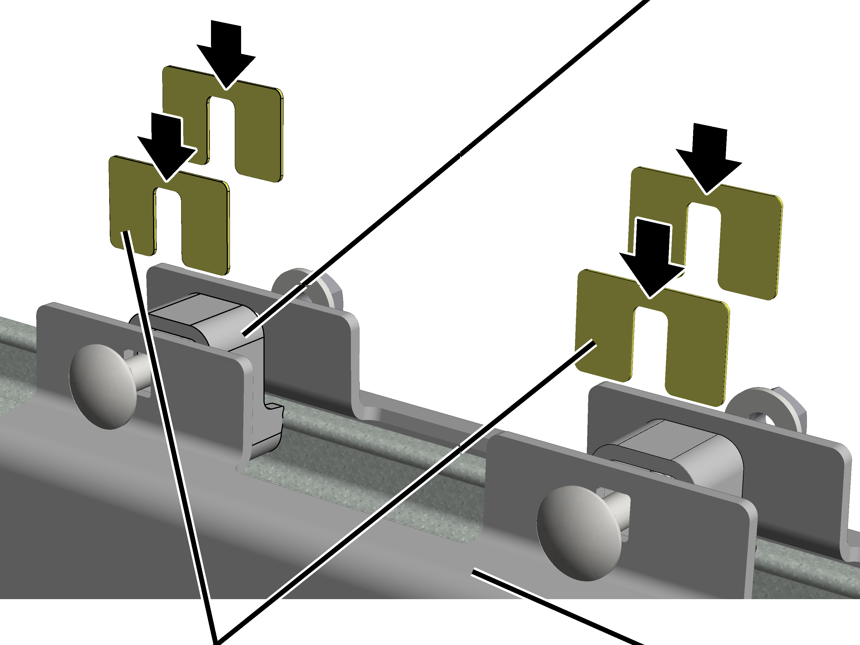
|
|
Spacer part |
|
| |
|
U-shaped plates |
Clamping plate |
Slightly loosen all
hexagonal nuts on the cup square bolts.
● The clamping plates (2x) move apart at the top at the spacer parts.
Insert a U-shaped plate
from above on the left and right next to all spacer parts.
The plates always have to be inserted on the left and right and always on all four spacer parts.
The plates must be inserted until they are flush with the top edge of the spacer parts.
Screw the hexagonal nuts
on. 120 Nm.
● The plates keep the clamping plates on the profile head somewhat further apart. Thus the profile rail sections at the travel gap will not bend as far apart.
Check the travel gap
again.