Profile joint
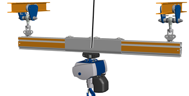
In the following steps, the crane girder of the EHB-I is pre-installed on the ground.
|
Profile joint |
|
|
The connected profile rail sections must be able to be raised and brought underneath the suspensions safely and without posing additional hazards.
|
|
The figures show the installation of an aluminium HB profile rail of size HB150A. The installation of larger or smaller HB profile rails does not differ significantly from this. |
 The profile rail sections
must be laid out on the building floor the way they are to be later installed.
The profile rail sections
must be laid out on the building floor the way they are to be later installed.
|
|
The position of the profile rail sections is specified in the planning documents. |
The specified dimensions, positions and clearances must be followed exactly.
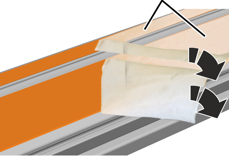
The profile rail sections are laminated at the sides. The protective film is removed before further assembly.
|
|
Protective film |
|
| |
Pull off the protective
film at a sharp angle from the side lamination.
|
|
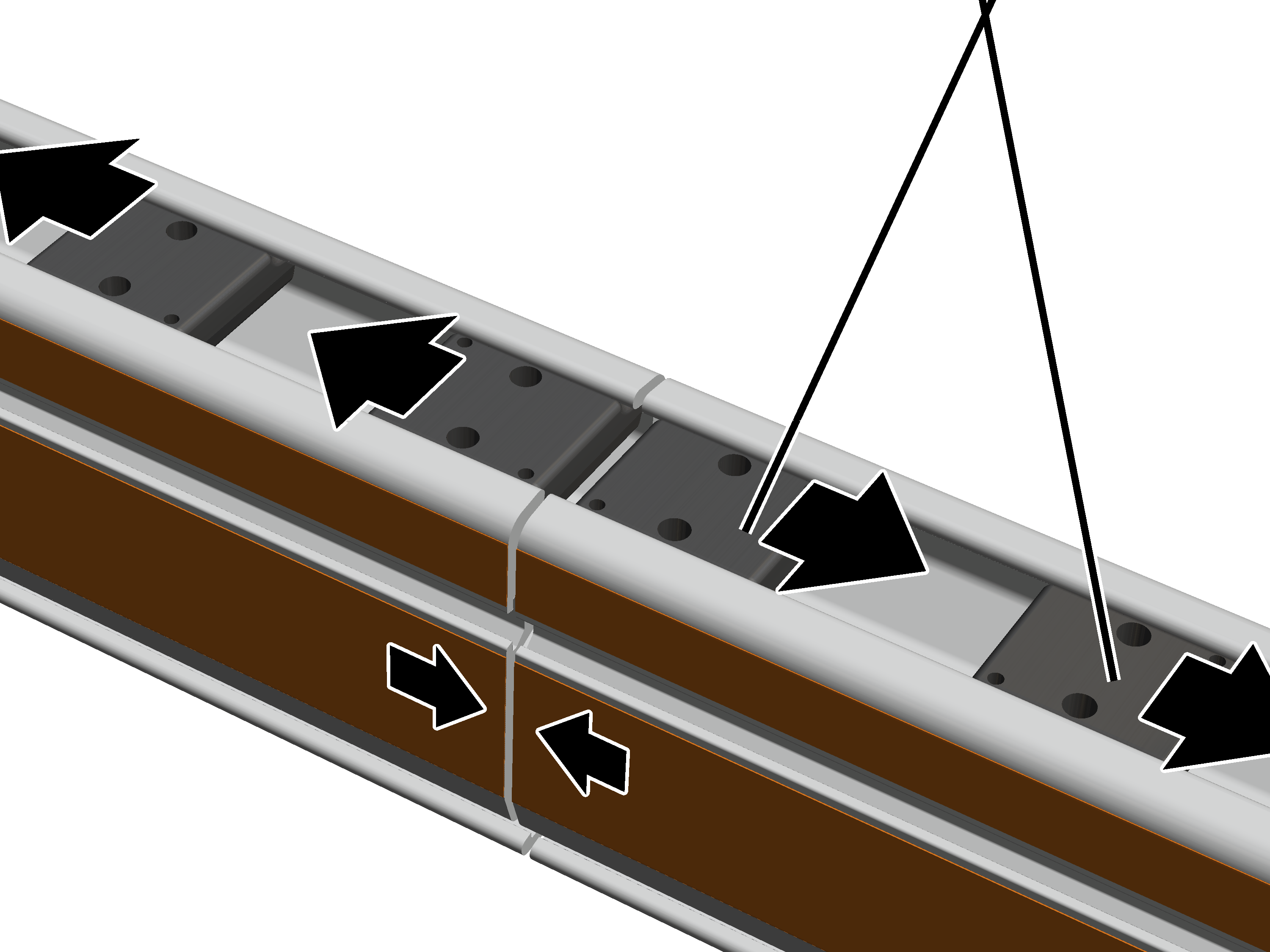
Head nut |
|
| |
Insert two head nuts each
in the left and right profile rail sections.
Lay the profile rail
sections to one another.
The profile rail sections can be directly flush to one another. The must not be more than 2 mm apart.
This work step only applies if a crane girder suspension is intended in the area of the clamping plates on a profile joint.
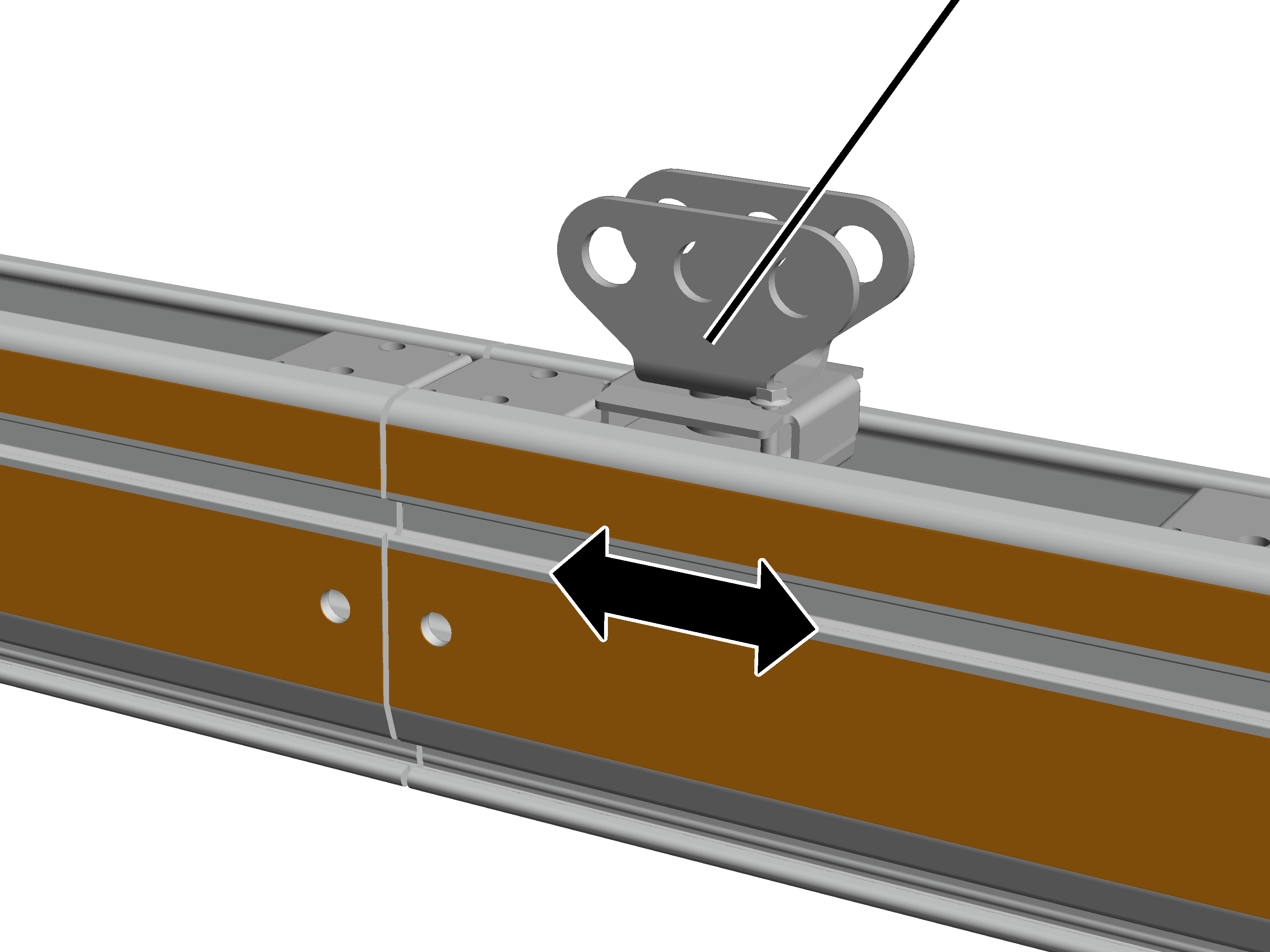
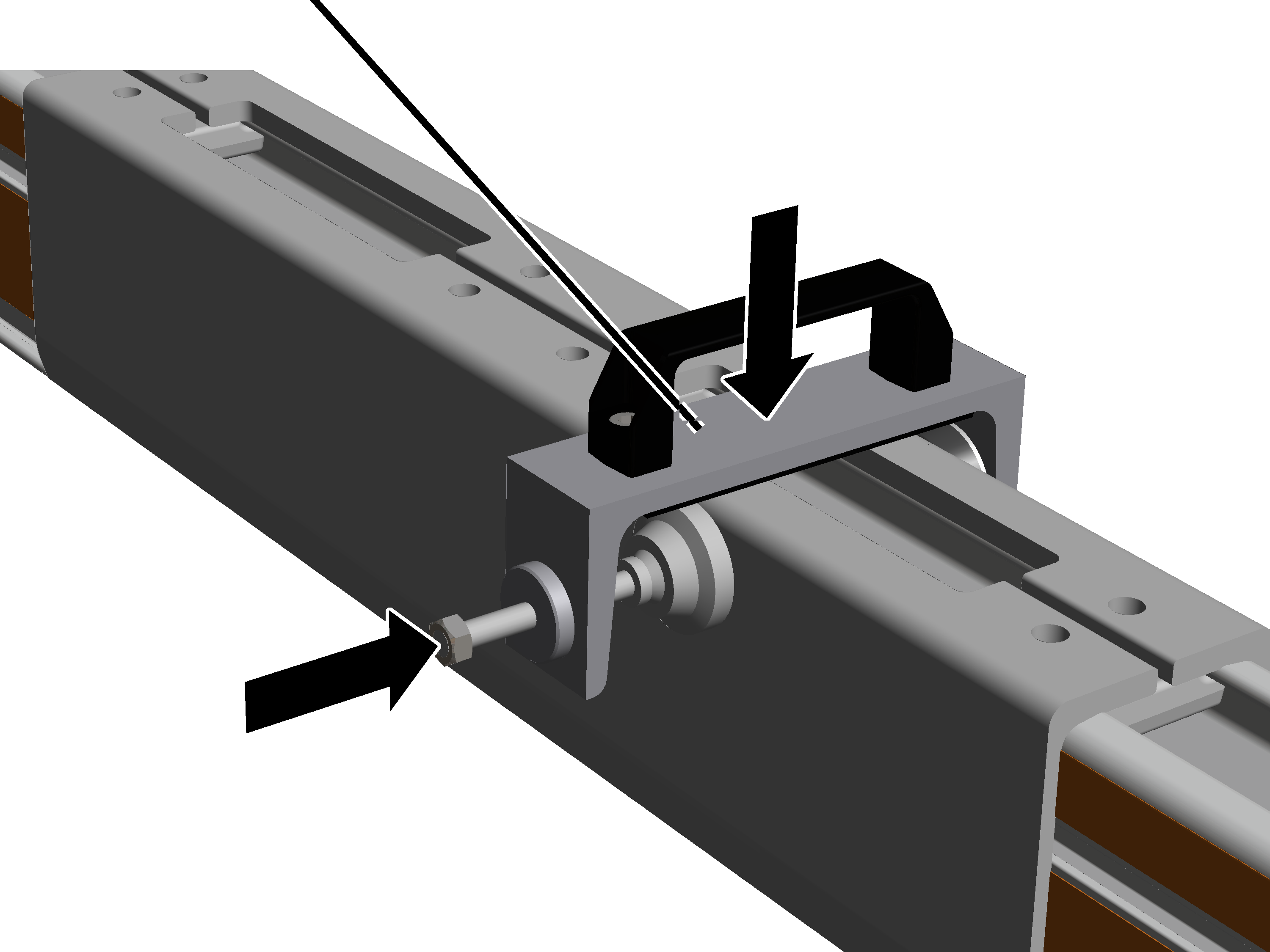
The crane girder suspension can also be installed in the area of a profile joint. To do this, the profile connection must first be pushed precisely to the position at which it will later be screwed tight.
|
|
Profile connection |
|
| |
 Push the profile
connection to its intended position.
Push the profile
connection to its intended position.
Once the clamping plate has been installed in the next step, the profile connection can no longer be shifted.
|
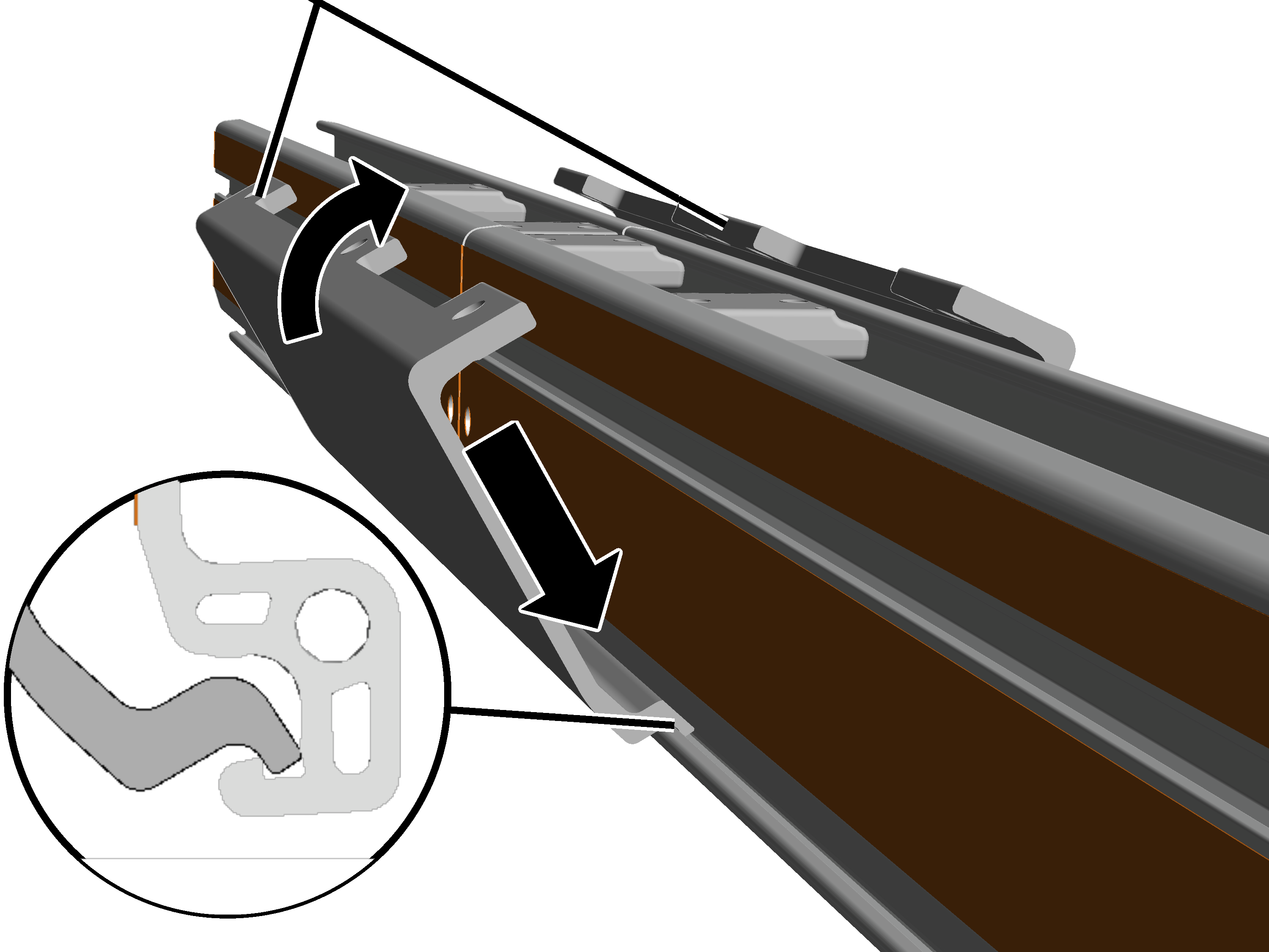
Clamping plates |
|
|
| |
Tilt the clamping plate
slightly and insert it below in the profile rail section.
When doing this, insert the bottom of the clamping plate behind the edge on the profile rail section.
Position the clamping
plate so that it is exactly centred between the two profile rail sections.
Press the clamping plate
together at the top.
● At the bottom the clamping plate presses from the inside against the edge of the profile rail section.
This work step only applies if a crane girder suspension is intended in the area of the clamping plates on a profile joint.
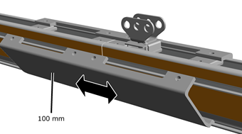
Only with a crane girder suspension in the area of a profile joint: The clamping plates do not need to be inserted exactly centred on the profile joint. The clamping plates may be shifted up to 100 mm to the left or right so that the crane girder suspension can lie at the exactly desired position.
Note:
For a profile joint without a crane girder suspension, the clamping plates must be installed exactly centred!
|
|
Only with a crane girder
suspension in the area of a profile joint: The clamping plates can be shifted up
to 100 mm.
Check the spacing of the
profile rail sections again.
The profile rail sections can be directly flush to one another. The must not be more than 2 mm apart.
|
Assembly aid |
|
|
| |
Press the clamping plates
together to such an extent that the assembly aid can be set in place.
Place the assembly aid on
the clamping plate.
The assembly aid can be obtained from ABUS Service. AN 316469.
Alternatively, a screw clamp with suitable base (e.g. rubber mat) can be used.
Screw the assembly aids
together until the clamping plates can clearly be heard to latch into place at
the sides.
The clamping plates must be clearly heard to latch in place on both sides and at both profile rail sections.
If necessary: use the assembly aid to press the clamping plates together at the other end as well until they can clearly be heard to latch into place.
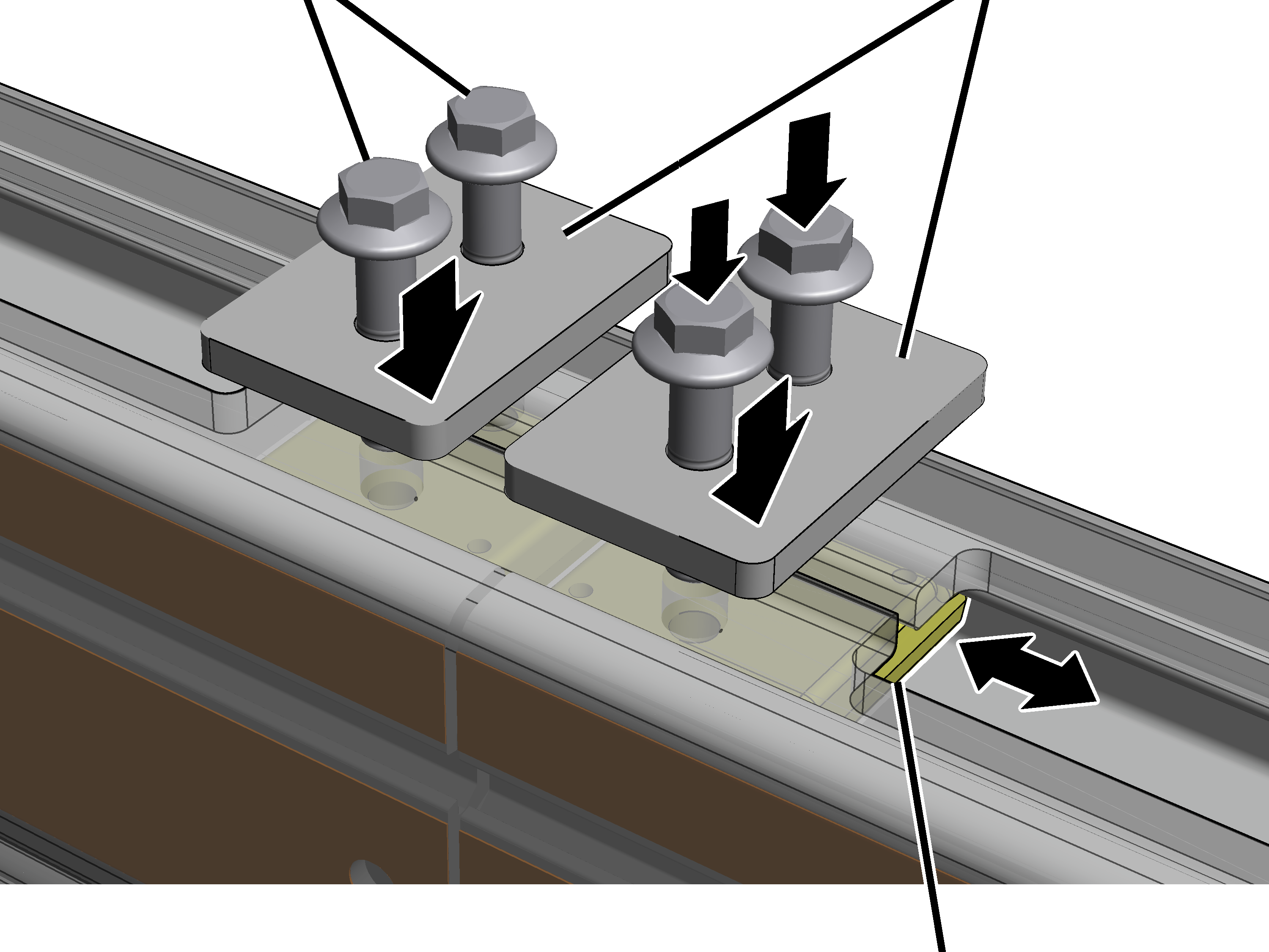
At all four head nuts:
|
Rib screw M12x50 |
Metal plate |
|
| |
|
|
Head nut |
Position the head nut
until it is exactly underneath the clamping plate bracket.
Place the plate on the
drilled holes in the clamping plate.
Insert the rib screws
M12x50 (2x per profile holder) through the plate and the clamping plate and
screw into the head nut.
Screw in the rib screws.
130 Nm.
This work step only applies if a crane girder suspension is intended in the area of the clamping plates on a profile joint.
Screw in the rib screws of
the profile connection on the clamping plate (2x).
|
Size |
Rib screw |
Tightening torque |
|
HB150 |
M6x40 |
20 Nm |
|
HB190 |
M6x40 |
20 Nm |
|
HB240 |
M6x40 |
20 Nm |