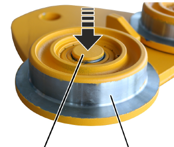
Bolt
Wheel
If the wheel is damaged or worn, it must be replaced by a new wheel.
This section shows how to change a non-driven wheel. The procedure to change a driven wheel does not differ significantly from this. Additional work steps are marked with a dashed line.
|
| |
|
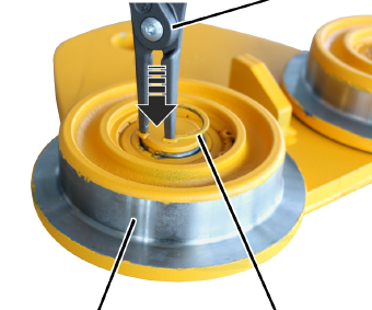
Bolt |
Wheel |
 Hammer the wheels (2x)
onto the bolt.
Hammer the wheels (2x)
onto the bolt.
|
|
Pliers |
|
| |
|
Wheel |
Circlip |
Insert circlips (2x) into
the inner wheels using pliers.
|
| |
|
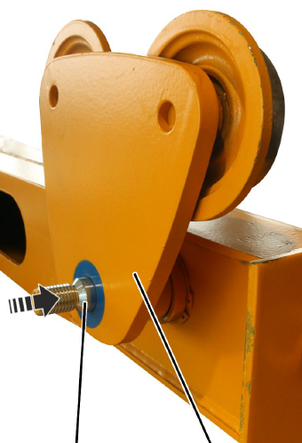
Threaded bolts |
Side panel |
Push the side panel onto
the threaded bolt on the end carriage.
|
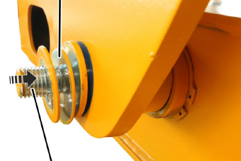
Spacer discs |
|
|
| |
|
Threaded bolts |
|
Slide the spacer discs
onto the threaded bolt.
Note
The number of spacer discs determines the flange width on the
travel mechanism.
The difference between the spacer discs on the left and
right side of the threaded bolt on the end carriage must not exceed 2.5 mm.
That is the equivalent of 1 thin spacer disc.
|
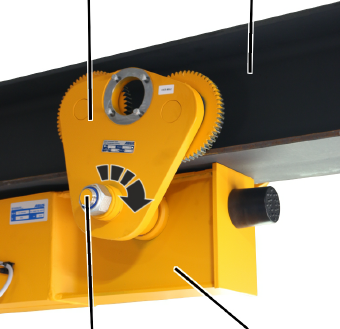
Side panel |
Crane track |
|
| |
|
Self-locking nut |
End carriages |
Tighten the self-locking
nut.
Make sure when doing this that the spacer discs sit flush.
|
Travel mechanism |
Self-locking nut |
Tightening torque |
|
DL 80 |
M20 |
130 Nm |
|
DL 112 |
M24 |
160 Nm |
|
DL 140 |
M36 |
220 Nm |
|
|
Crane track |
|
| |
|
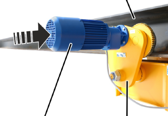
Drive |
Side panel |
Slide the drive in the powered side
panel.
Bolt on the drive with the
rib screws M6x20 (4x). Tighten to 10 Nm.
|
|
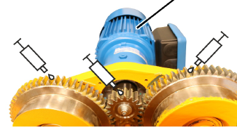
Drive |
|
| |
Lubricate all three gear rims. Apply a liberal coating of
lubricant using a brush.
Recommendation: Multi-purpose grease “High-Lub LT1 EP”, item number 317880.
Alternative: Multi-purpose grease “High-Lub”, item number 318490 (cartridge with 400 g).
Only with contactor control:
|
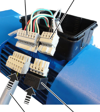
Pin
multipoint |
Pin
multipoint |
|
| |
|
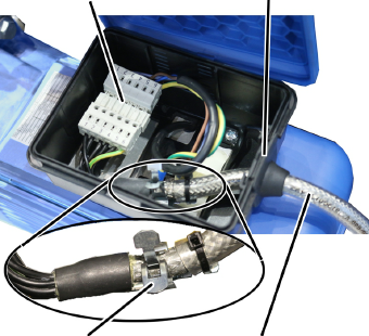
Connection cable of drive |
Rectifier for brake |
Insert the connection cable for the drive in
the pin multipoint connector on the drive.
Insert the rectifier for
the brake in the pin multipoint connector on the drive.
Lay the plug-in
connections and connection cable in the connector housing.
|
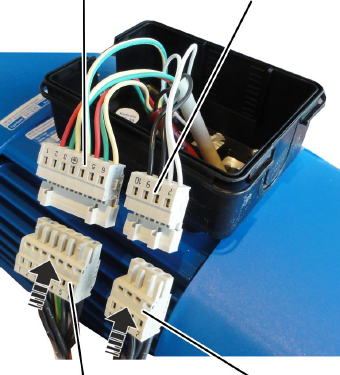
Pin
multipoint |
Pin
multipoint |
|
| |
|
Bush
multipoint connector |
Bush
multipoint connector |
Insert the bush multipoint
connector for the drive on the pin multipoint connector on the drive.
Insert the bush multipoint
connector for the brake on the pin multipoint connector on the drive.
|
Plug-in connection |
Cable bushing |
|
| |
|
Screening clamp connection |
Connection cable |
Push the front end of the
connection cable (where the sheathing around the shield has been removed) into
the screening clamp connection.
Fasten the connection
cable to the screening clamp connection using cable ties.
Lay the plug-in
connections and connection cable in the connector housing.
|
|
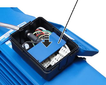
Intermediate plate |
|
| |
Press the intermediate
plate in.
Close the housing
cover.