Compare the operating voltage
and frequency range on the type plate with the mains voltage and frequency of
the local grid.
Compare the operating voltage
and frequency range on the type plate with the mains voltage and frequency of
the local grid.If the drive is to be connected to an ABUS crane installation, read on for further instructions. If the drive is to be connected to a different installation: see Connecting the drive to a non-ABUS crane.
Compare the operating voltage
and frequency range on the type plate with the mains voltage and frequency of
the local grid.
|
| |
|
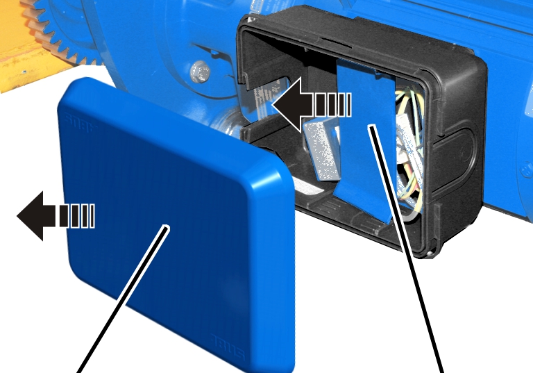
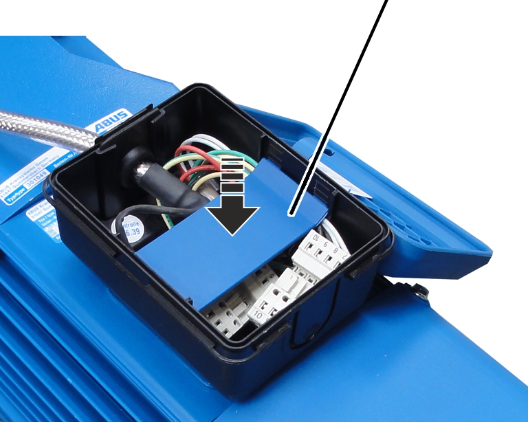
Housing cover |
Intermediate plate |
Open the housing cover.
Take out the intermediate
plate.
|
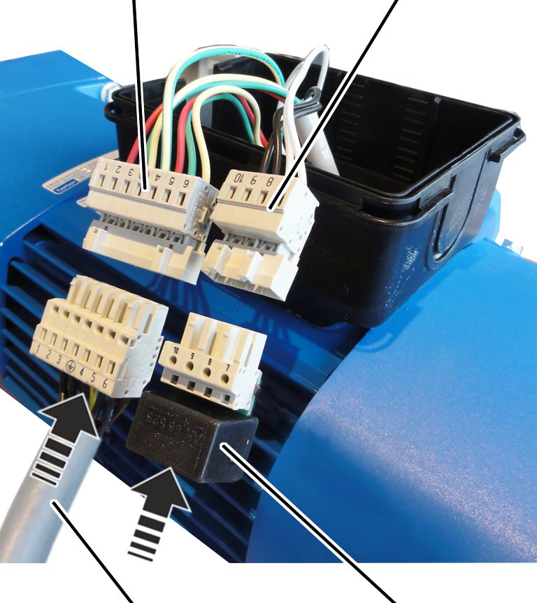
Pin multipoint connector on the drive |
Pin multipoint connector on the drive |
|
| |
|
Connection cable of drive |
Rectifier for brake |
Insert the connection cable for the drive in
the pin multipoint connector on the drive.
Insert the rectifier for the
brake in the pin multipoint connector on the drive.
Lay the plug-in connections and
connection cable in the connector housing.
|
Pin
multipoint |
Pin
multipoint |
|
| |
|
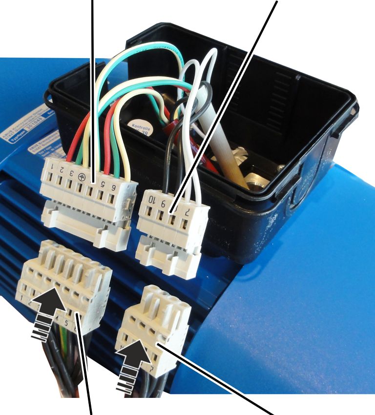
Bush multipoint connector for drive |
Bush multipoint connector for drive |
Insert the bush multipoint connector for the
drive on the pin multipoint connector on the drive.
Insert the bush multipoint
connector for the brake on the pin multipoint connector on the drive.
|
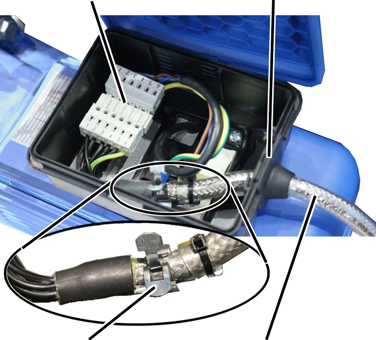
Plug-in connection |
Cable bushing |
|
| |
|
Screening clamp connection |
Connection cable |
Push the front end of the
connection cable (where the sheathing around the shield has been removed) into
the screening clamp connection.
Fasten the connection cable to
the screening clamp connection using cable ties.
Lay the plug-in connections and connection
cable in the connector housing.
|
|
Intermediate plate |
|
| |
Press the
intermediate plate in.
Close the housing cover.
Once the crane installation is ready for operation:
Test the function of the
electric trolley.
If the drive runs in the wrong direction:
● Two phases in the power line of the crane installation are interchanged.
If possible, correct the
interchanged phases in the power line of the crane installation.
Otherwise:
Switch two phases on the
connection cable of the drive.