Installing the trolley power
supply
If the trolley towing
arm has not been installed yet, continue here. Otherwise, skip this
section.
The trolley towing arm is installed above the hoist panel. It
pulls the electrical cables for the trolley power supply (festoon cable system
or energy chain) and the cross-type limit switch of the trolley travel limit
switch back and forth parallel to the trolley.
The trolley towing arm must be installed differently,
depending on the main girder (I-beam or box girder) and the type of power supply
(festoon cable system or energy chain).
Mounting the
trolley towing arm
Only with trolley D, DA or
DB and energy chain
This section only applies if a trolley of construction D, DA,
or DB is connected to an overhead travelling crane with an energy chain.
The component
parts of the trolley towing arm are enclosed loose and must be
assembled.
|
Pipe clamp |
Mount |
|
|
|
Square
tube |
Threaded
bracket |
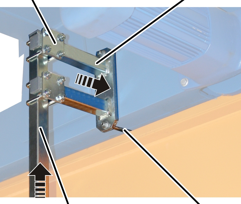
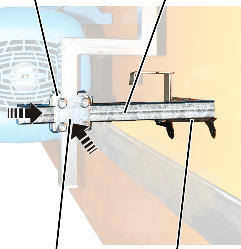
 Screw the mount to the end
carriage using the threaded bracket and rib nuts (2x).
Screw the mount to the end
carriage using the threaded bracket and rib nuts (2x).
|
Threaded bracket |
Tightening torque |
|
M8 |
25 Nm |
|
M10 |
50 Nm |
|
M12 |
75 Nm |
Screw the square tube to the
mount using two pipe clamps. 15 Nm.
|
Rectangular pipe clamp |
Individual components of the energy chain |
|
|
|
Pipe
clamp |
Carrying
tube |
Screw the carrying tube with
pipe clamp and rectangular pipe clamp onto the vertical square tube (trolley
towing arm). 15 Nm.
Fasten the individual components of the energy chain
(deflection bracket and connection element) with bolts and SL safety clip to the
carrying tube.
|
Cable
ties |
Flat
cable |
|
|
|
Connection element |
Energy
chain |
|
|
|
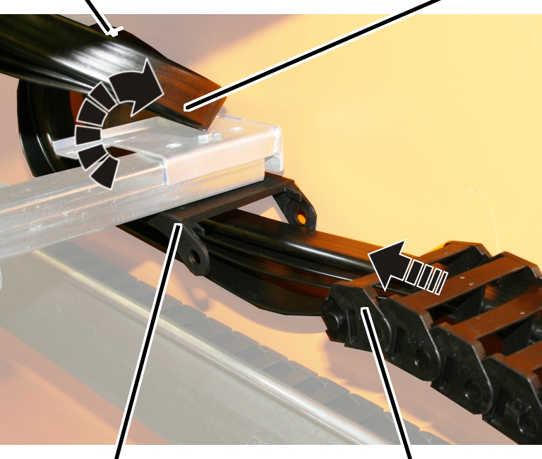
 Lead through the flat cable from
the energy chain and guide in a curve around the deflection bracket.
Lead through the flat cable from
the energy chain and guide in a curve around the deflection bracket.
Fasten the flat cable with cable
ties to the upper section of the deflection bracket.
Insert the energy chain into the
connection element and click into place.
Only for trolley DQA
and
energy chain
This section only applies if a trolley of construction DQA is
connected to an overhead travelling crane with an energy chain.
The component parts of the trolley towing arm are enclosed
loose and must be assembled.
|
|
Mounting
plate |
|
|
|
Carrying tube |
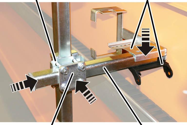
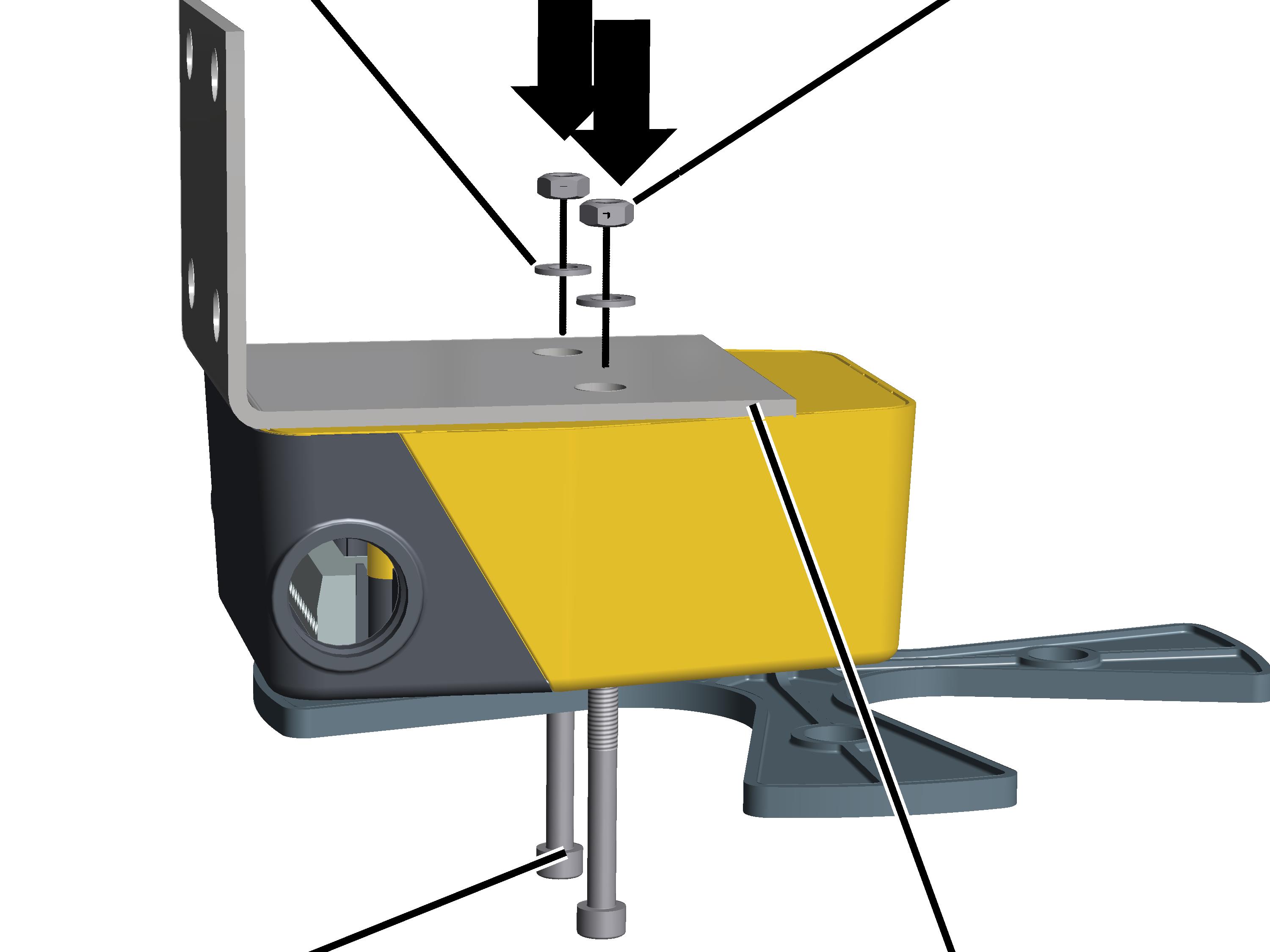
Insert the carrying tube from
below into the trolley frame.
Screw on the mounting plate with
a hexagonal head screw M8 and hexagonal nut.
Insert the carrying tube between
the mounting plate and the trolley frame.
Tightly screw on the hexagonal
nuts. 25 Nm
|
Rectangular pipe clamp |
Carrying
tube |
|
|
|
Pipe
clamp |
Individual components of the energy
chain |
Screw the horizontal carrying
tube with pipe clamp and rectangular pipe clamp onto the vertical carrying tube
(trolley towing arm). 15 Nm.
Fasten the individual components
of the energy chain (deflection bracket and connection element) with bolts and
SL safety clip to the square tube.
|
Cable ties |
Flat
cable |
|
|
|
Connection element |
Energy
chain |
|
|
|
Lead through the flat cable from
the energy chain and guide in a curve around the deflection bracket.
Fasten the flat cable with cable
ties to the upper section of the deflection bracket.
Insert the energy chain into the
connection element and click into place.
Only for an overhead
travelling crane with a festoon cable system
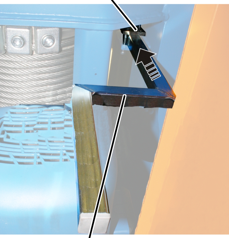
The trolley towing arm is fastened pre-installed to the
C-rail system and must be fitted to the trolley.
For trolleys with trolley travel limit switches: the trolley
travel limit switch is already completely installed.
|
|
Trolley
towing arm |
|
|
|
Marking |
|
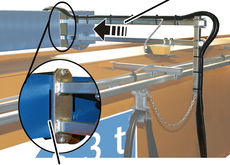
Attach the installed trolley
towing arm to the end carriages.
In most cases, the end carriage has a marking at which the
trolley towing arm is to be attached. The switching point of the trolley travel
limit switch is already adjusted for this position and the cable lengths
correspondingly adapted.
Screw the trolley towing arm
tightly with the threaded bracket and rib nuts (2x).
|
Threaded bracket |
Tightening torque |
|
M8 |
25 Nm |
|
M10 |
50 Nm |
|
M12 |
75 Nm |
Installing the
cross-type limit switch on the trolley towing arm
Only with cross-type limit
switch
This section only applies if
the wire rope hoist has a cross-type limit switch in the trolley travel
direction.
Where and for which travel limit the cross-type limit switch
is designed is specified on the wiring diagram.
Installing the
cross-type limit switch
|

|
Danger due to malfunction!
If the cross-type limit switch is screwed on too
tightly, the parts on the inside can become jammed and no longer function
properly.
The tightening torque of 3 Nm must be
strictly observed. |
|
Locking
washer |
Hexagonal nut |
|
|
|
Fillister-head screw M5x50 |
Mounting
bracket |
Screw the mounting bracket onto
the cross-type limit switch with the fillister-head screws M5x50 (2x).
Screw on the mounting bracket
using locking washers and M5 hexagonal nuts (2x). 3 Nm.
Installing the
cross-type limit switch
The cross-type limit switch is normally
installed on the trolley towing arm.
|
Pipe
clamp |
|
|
|
|
Cross-type limit switch |
|
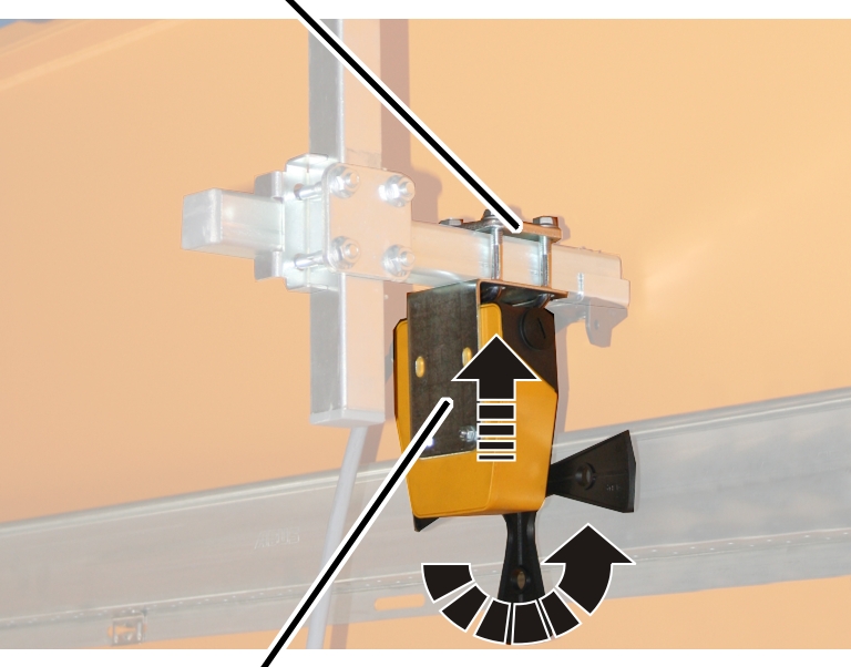
Turn the
cross-type limit switch to position 0.
The position of the cross-type
limit switch is marked with an arrow that can be rotated further, depending on
the switching state.
Move the cross-type limit switch
onto the square tube in such a way that the switching lug activates the
cross-type limit switch.
Screw in the cross-type limit
switch with pipe clamps (2x) tightly. 15 Nm.
Route the connection cable
(round cable or flat cable) from the cross-type limit switch to the panel.
Route the connection cable with
cable fitting into the panel.
If necessary, connect the
connection cable to a coupler plug or connector.
Fasten connection cable with
cable ties, cable grips and adhesive clips.
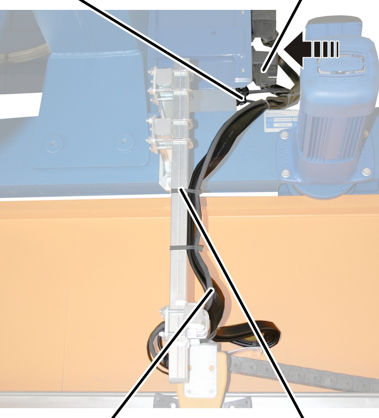
Connecting the
trolley power supply
|
Cable
fitting |
Connectors and coupler plugs |
|
|
|
Connection cables |
Cable
ties |
Lay the connection cable leading
from the energy chain along the square tube to the hoist panel.
Fasten the connection cables
neatly separated with cable ties.
Plug the connector and coupler
plugs into the hoist panel, or guide the connection cables through cable
fittings and into the hoist panel.