Comply with occupational health and safety requirements.
If the wheel is damaged or worn, it must be replaced by a new wheel.
Comply with occupational health and safety requirements.
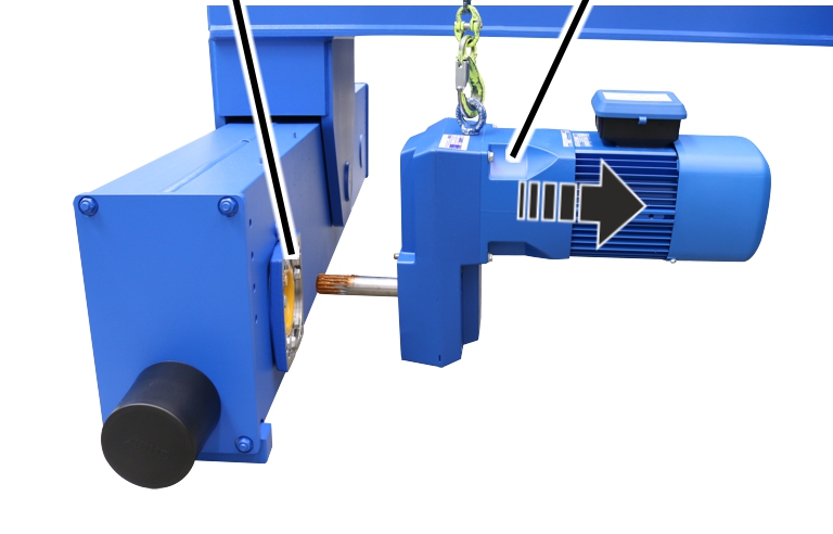
Relieve the load of the end carriage on the wire rope hoist near the
wheel from below.
|
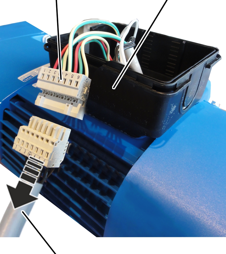
Coupling |
Connector housing | |
|
| ||
|
Connection cable |
| |
 Open the connector housing to the drive.
Disconnect the connection cable from the coupler plug.
Determine the weight of the drive. See the ABUS Drive product manual.
Secure the drive so that the weight can be held safely and the output
shaft will not be subject to load (e.g. insert in round sling).
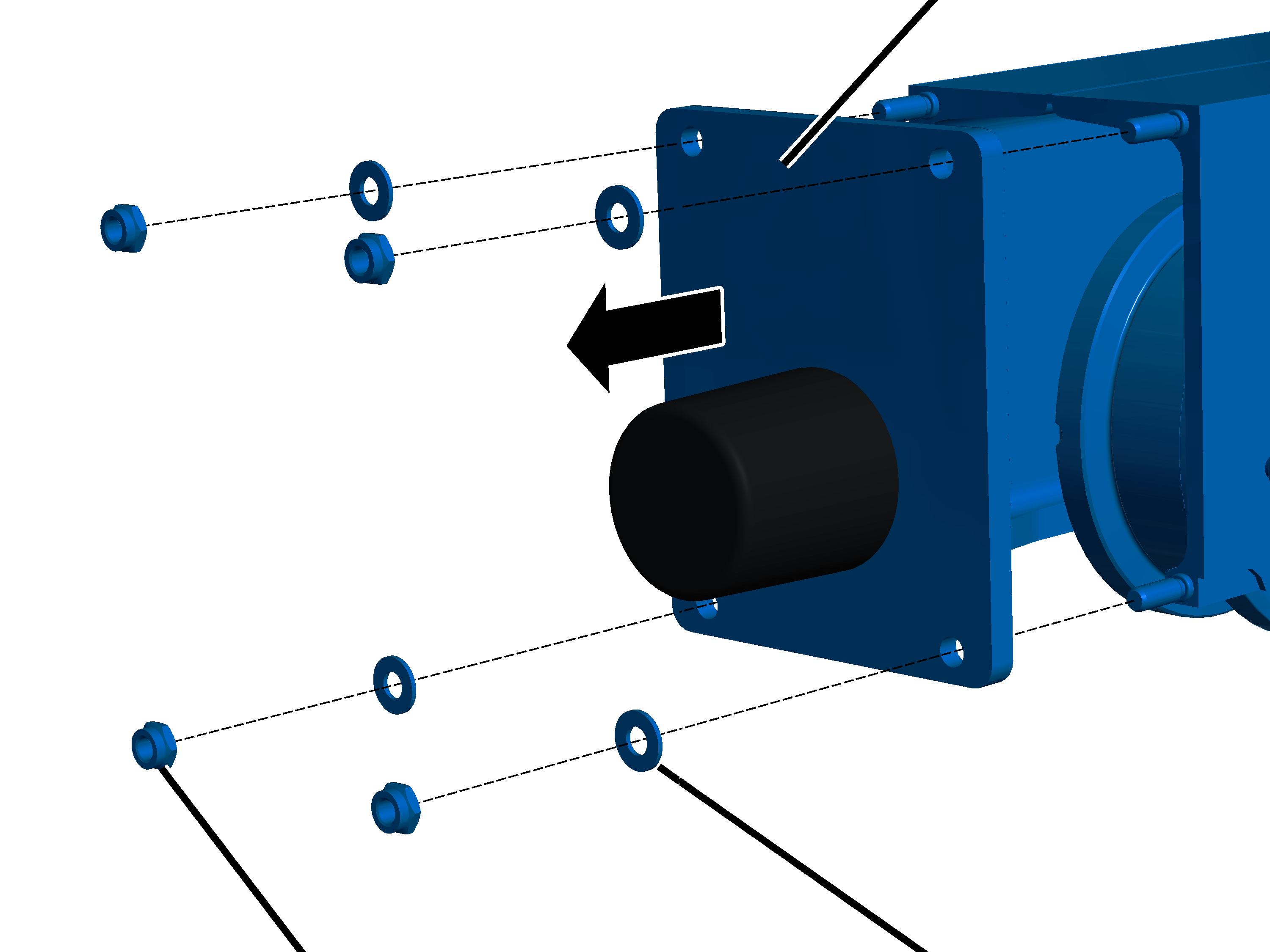
This section only applies if an AZP drive is to be removed.
|
| |
|
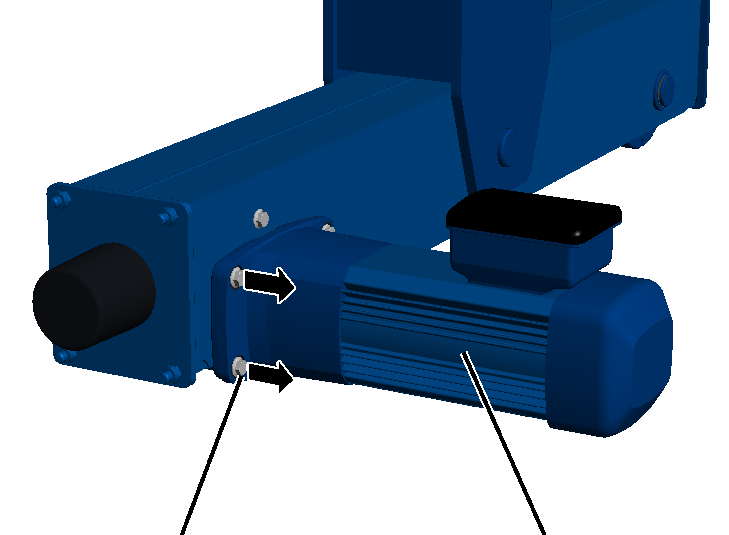
Rib screws |
Drive |
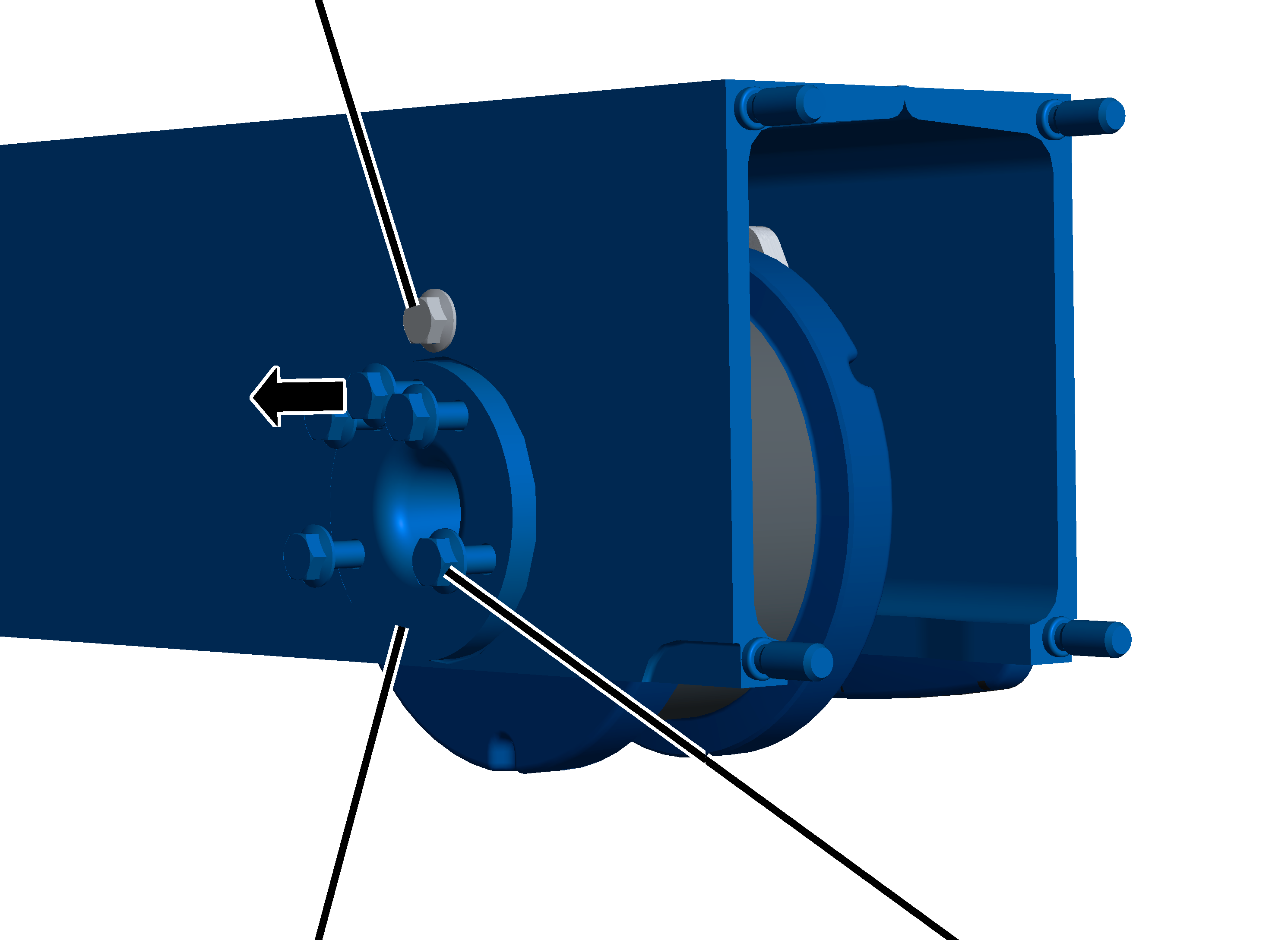
Release the rib screws (4x).
|
| |
|
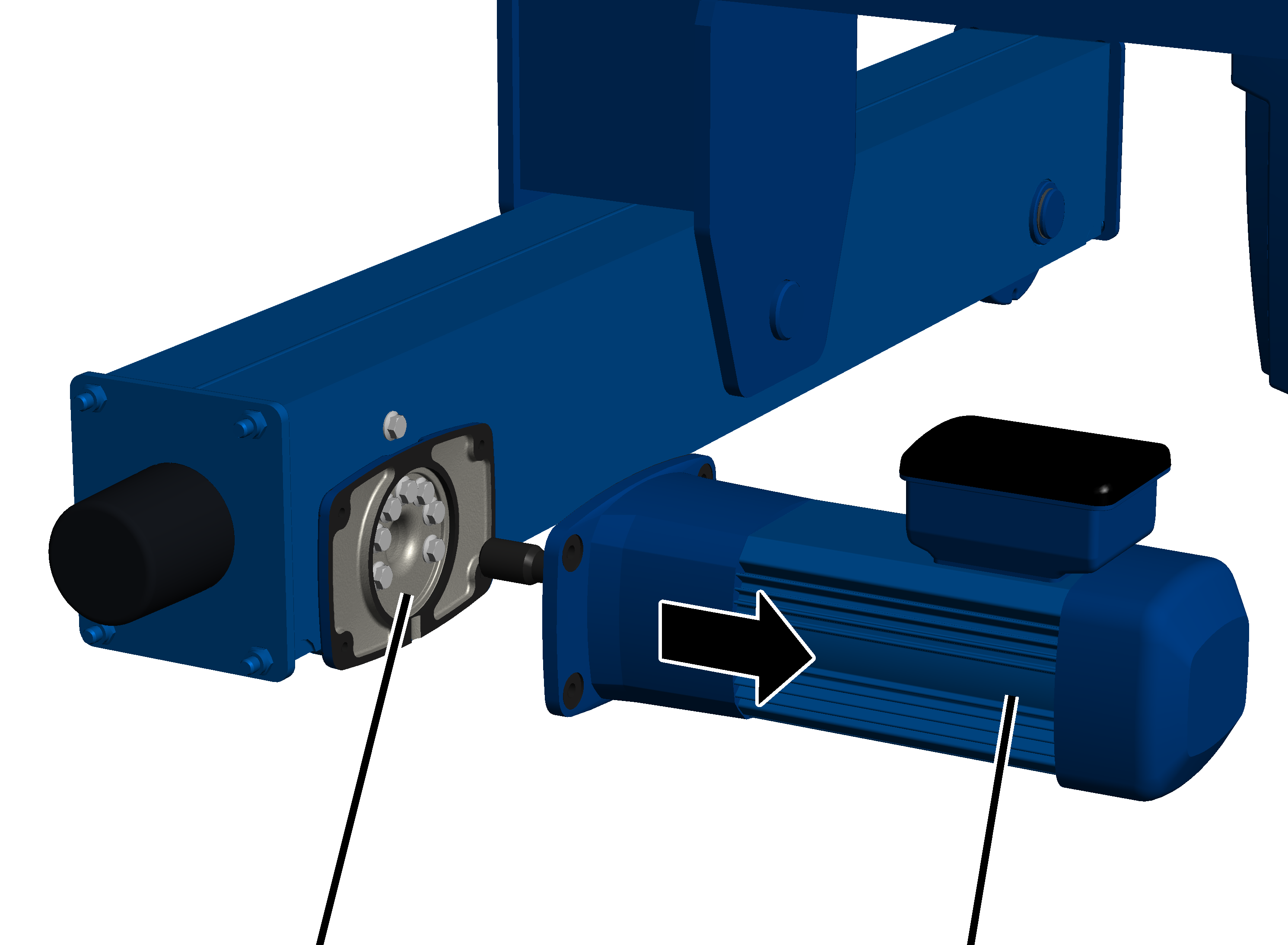
Bearing flange |
Drive |
Pull out the drive.
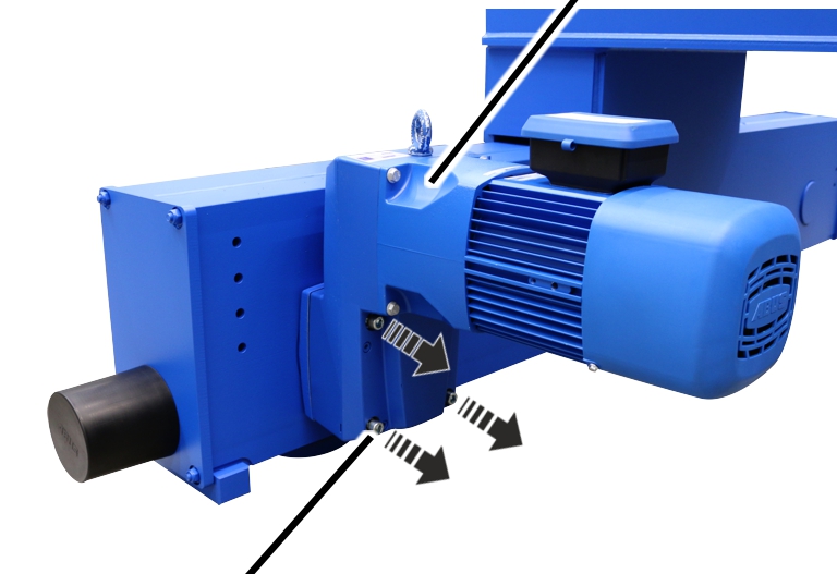
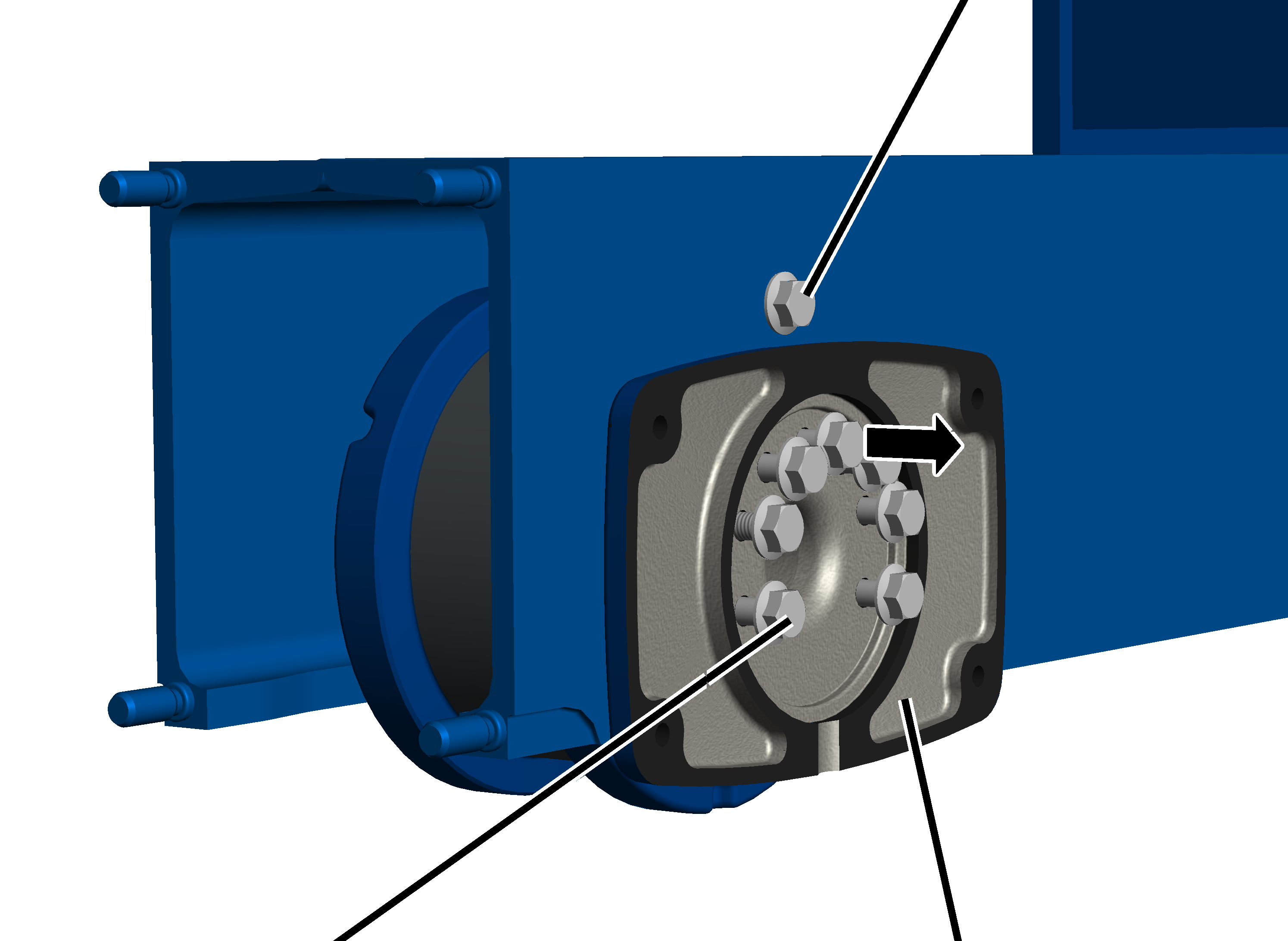
This section only applies if an AZF drive is to be removed.
|
|
Drive |
|
| |
|
Fillister-head screws |
|
Loosen the fillister-head screws (4x).
|
Bearing flange |
Drive |
|
| |
Pull out the drive.
|
|
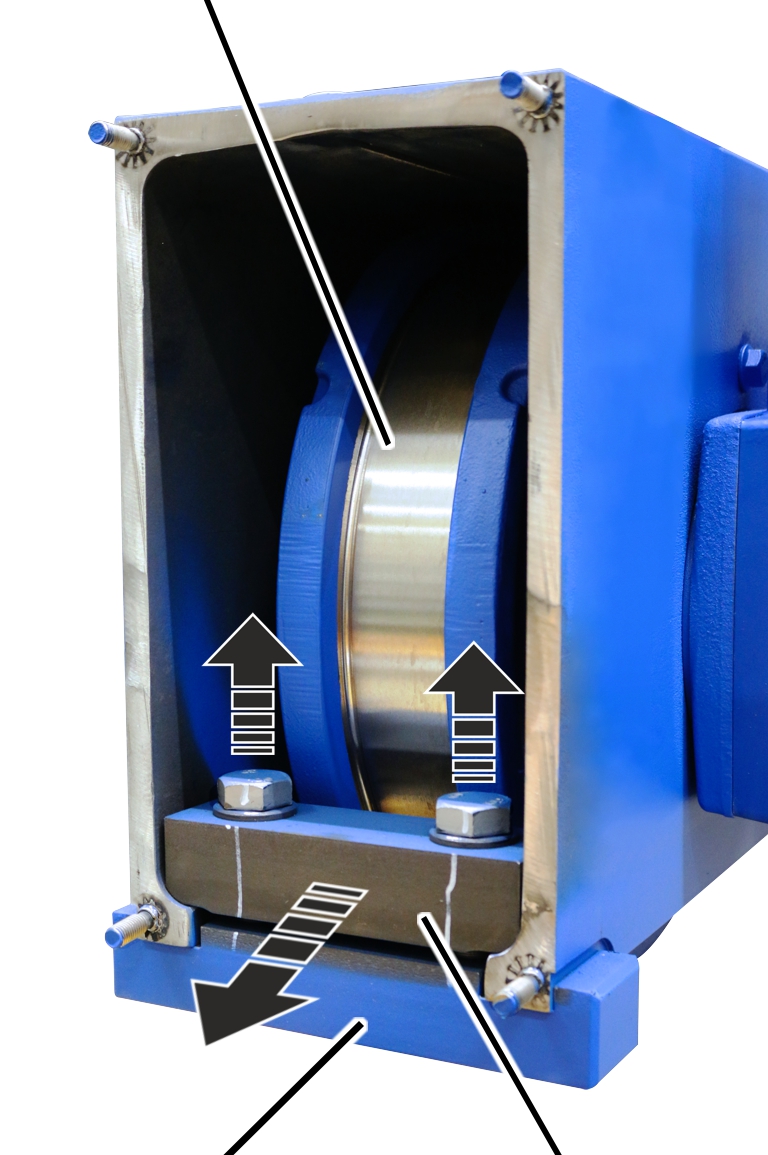
Buffer plate |
|
| |
|
Self-locking nut |
Plastic washer |
Unscrew the self-locking nuts (4x).
From size 160: remove the plastic washers (4x).
Remove the buffer plate.
Trolleys in size 280, 350 and 420 have a clamping piece installed on the driven wheel in the end carriage. To remove the wheel, the clamping piece must be removed.
|
Wheel |
|
|
| |
|
Clamping piece |
Bracket |
Loosen screws (2x).
Take out the bracket with the clamping piece.
|
|
Retaining screw |
|
| |
|
Rib screw |
Bearing flange |
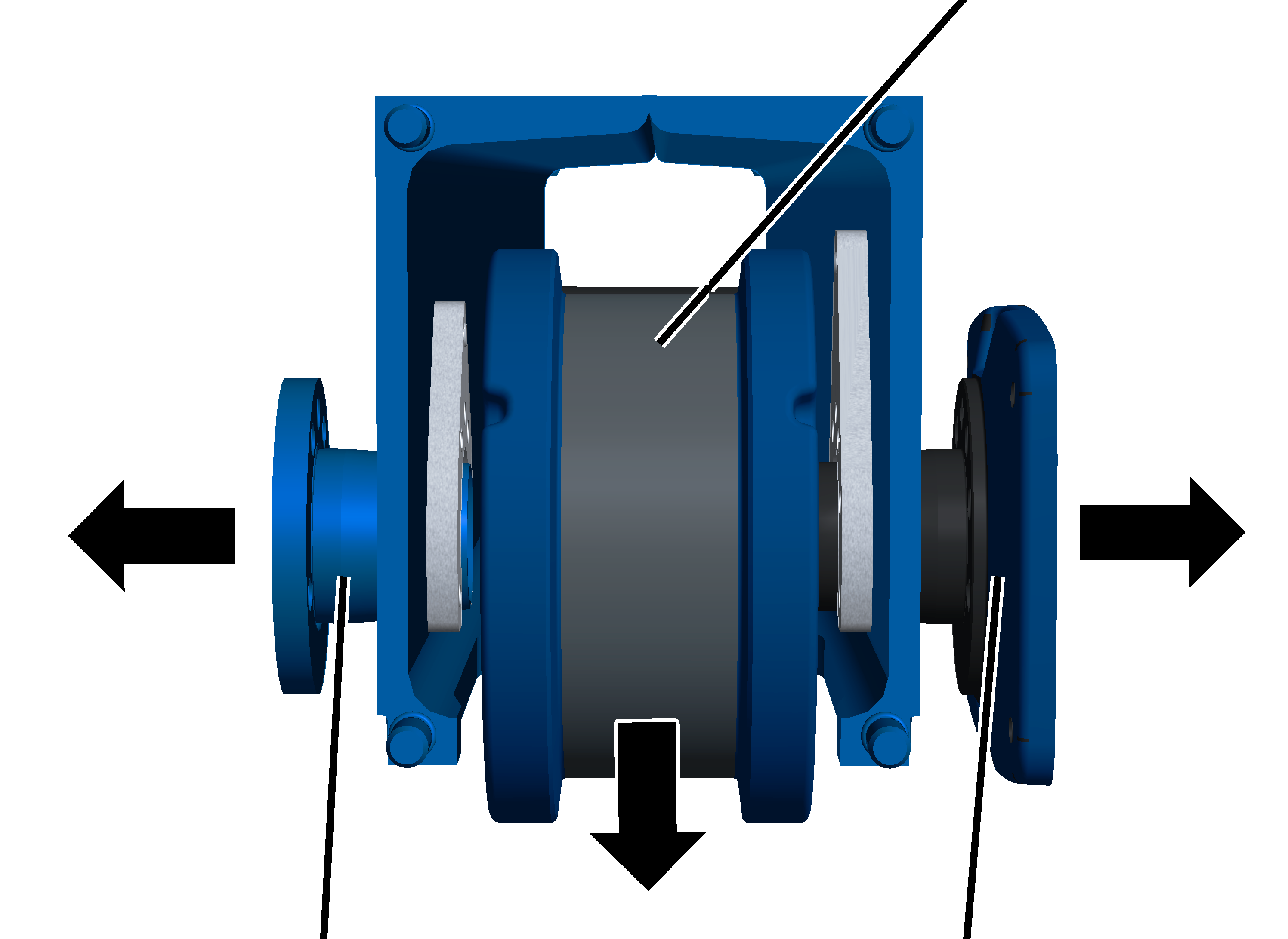
|
Retaining screw |
|
|
| |
|
Bearing bolt |
Rib screw |
|
|
Wheel |
|
| |
|
Bearing bolt |
Bearing flange |
Take out the bearing bolt, bearing flange and wheel.
Note
Only for size 420 with drive 420V: an adapter is also inserted on the bearing flange. If this cannot be easily taken off, it can remain on the bearing flange when the wheel is removed.
Tip:
To be able to easily remove the bearing flange from the end carriage, screw two or four screws in the corners of the bearing flange and thereby press the bearing flange off the end carriage.