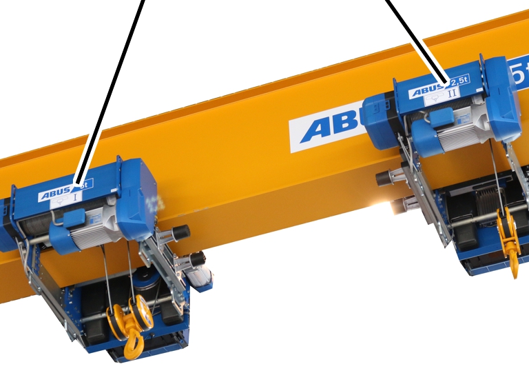
The crane is equipped with two trolleys. These can be
controlled using a joint pendant control (or transmitter). This improves safety
during the transportation of e.g. long or bulky loads.
Assigning the
trolleys
Only with ABUS Electrics 3
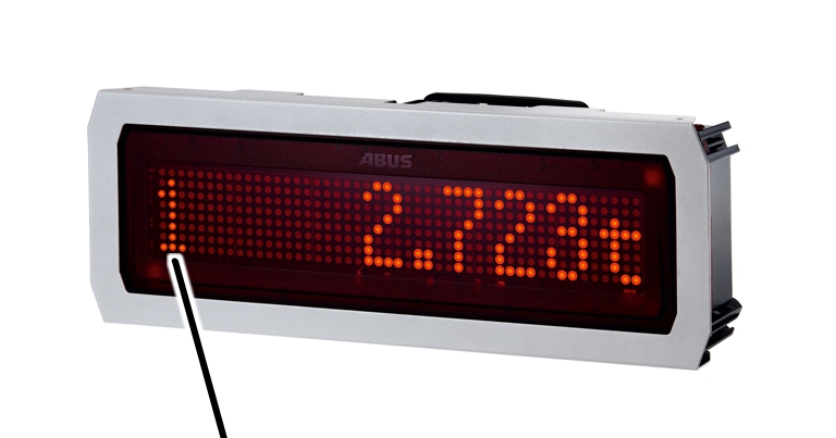
with LED matrix display
When fitted to a trolley, the LED matrix display can also
show the numbers “1” and “2” to indicate the trolley assignment.
|
|
|
Number
of the trolley |
|
● The
assigned number of the trolley is displayed at the foremost position on the LED
matrix display.
|
Label “Trolley I” |
Label “Trolley II” |
|
|
● The
trolleys are labelled “Trolley I” and “Trolley II” on the wire rope hoist.
Switching
between trolley I and trolley II
On a crane with trolley selection, it is possible to switch
back and forth between trolley I and trolley II.
Only with ABURemote
See the ABURemote product manual.
Only with pendant
control
See the pendant control product manual.
Switching over
to joint operation
On a crane with trolley selection and joint operation, it is
also possible to switch back and forth between trolley I and trolley II in joint
operation of both trolleys.
Only with ABURemote
See the ABURemote product manual.
Only with pendant
control
See the pendant control product manual.
Only with ABUS Electrics
3
The control is without synchronisation control. This can
result in a change in the distance of the trolleys to one another, or in the
position of the load during transport, for example, due to different loads
placed on the drives with differing load distribution, to different braking
differences and to tolerances of the components.
If changes occur in the distance of the trolleys to each other or
in the position of the load:
 Allow the crane to come to a
complete standstill.
Allow the crane to come to a
complete standstill.
Switch to trolley I or trolley
II.
 Compensate for the changed
distance of the trolleys or the changed position of the load through
lifting/lowering or trolley travel to the right/left.
Compensate for the changed
distance of the trolleys or the changed position of the load through
lifting/lowering or trolley travel to the right/left.
Switch to joint operation
again.
Braking and
shut-down functions of the trolley travel limit switch, hoist limiter
In joint operation, the trolley travel limit switch and the
hoist limit switch are evaluated jointly.
If one of the trolley drives brakes or halts, or if one of
the hoists brakes or halts, the other trolley is also synchronously
controlled.
Only when turning loads
If the crane is to be used to turn loads, the overload
protection is possibly equipped with additional functions in order to also
detect an overload of the hoist even when it is lowering or stopped.
See the order-specific crane documentation.