Only with overhead
travelling cranes
Overview:
Electrical connection of the crane
─ The
power supply for the crane begins at the sub-distribution (8) of the mains
supply.
─ From
there, a line (7) runs to the mains switch (1) of the crane installation.
A mains switch is the best option for isolating the entire crane
installation.
The mains switch must be secured against inadvertent switching
back on.
The mains switch is usually located under the mains power supply
of the crane, e.g. on the building wall or on a building support or concrete
support.
─ From the
mains switch, the riser (2) extends to the feed unit (3).
─ The feed
unit connects the riser with the mains power supply (4) (usually a conductor
system) of the crane.
─ The
mains power supply contains a mobile current collector (5) which travels with
the crane along the crane track.
─ The
crane is connected to the mains power supply with the mains disconnector plug
(6).
This mains disconnector plug is used to isolate the individual
crane. The mains disconnector plug can be secured against inadvertent switching
back on.
Instead of the mains disconnector plug, a separate circuit
isolator (in the form a mains switch) can also be mounted on the crane
panel.
The function of the mains disconnector plug or circuit isolator
can also be fulfilled by a fuse isolating link. The fuse isolating link is
located in the crane control and can be secured against inadvertent switching
back on.
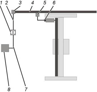
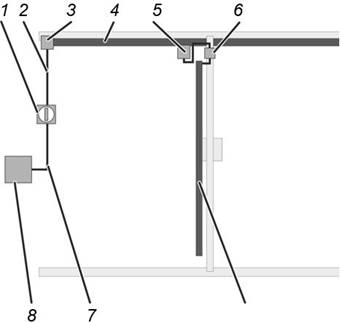
Only with pillar slewing jib
cranes
Overview:
Electrical connection of the crane
─ The
power supply for the crane begins at the sub-distribution (7) of the mains
supply.
─ From
there, a line (6) runs to the pillar base of the jib crane and is led through
the foundation into the pillar (1).
─ The line
runs to the mains switch (5) of the crane.
A mains switch is the best option for isolating the entire
crane.
The mains switch must be secured against inadvertent switching
back on.
The mains switch is located in the pillar at operating
height.
─ From the
mains switch, a line runs inside the pillar and is led out at the top.
For
types LS and LSX: The line is led directly out of the pillar.
For type VS:
The line runs in the pillar up to the slip ring (3).
─ For
types LS and LSX: The line out of the pillar is connected directly to the
trolley power supply (4). Depending on the control, the design may include a
housing with fuses for protection of the crane.
For type VS: From the slip ring, the line runs either to the jib
arm panel (2) and from there to the trolley power supply (4) or directly from
the slip ring to the trolley power supply. Depending on the control, the design
may include a housing with fuses for protection of the crane.
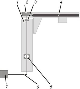
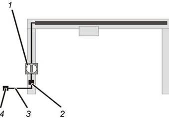
Only with wall jib
cranes
Overview:
Electrical connection of the crane
─ The
power supply for the crane begins at the sub-distribution (6) of the mains
supply.
─ From
there, a line (5) runs to the mains switch (4) of the crane.
A mains switch is the best option for isolating the entire
crane.
The mains switch must be secured against inadvertent switching
back on.
The mains switch is usually located under the crane, e.g. on the
building wall or on a building support or concrete support.
─ From the
mains switch, the riser (1) extends to the crane.
─ For
types LW and LWX: The line is connected directly to the trolley power supply
(4). Depending on the control, the design may include a housing with fuses for
protection of the crane.
For type VW: The line runs either to the jib arm panel (2) and
from there to the trolley power supply (4) or directly to the trolley power
supply. Depending on the control, the design may include a housing with fuses
for protection of the crane.
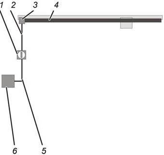
Only with HB crane types
monorail system and double-rail system
Overview:
Electrical connection of the HB crane
─ The
power supply for the HB crane begins at the sub-distribution (6) of the mains
supply.
─ From
there, a line (5) runs to the mains switch (1) of the HB crane installation.
A mains switch is the best option for isolating the entire HB
crane installation.
The mains switch must be secured against inadvertent switching
back on.
The mains switch is usually located under the mains power supply
of the HB crane, e.g. on the building wall or on a building support or concrete
support.
─ From the
mains switch, the riser (2) extends to the feed unit (3).
─ There
the line is connected with the trolley power supply (4). Depending on the
control, the design may include a housing with fuses for protection of the
crane.
Only with HB crane types
single-girder crane and double-girder crane
Overview:
Electrical connection of the HB crane
─ The
power supply for the HB crane begins at the sub-distribution (8) of the mains
supply.
─ From
there, a line (7) runs to the mains switch (1) of the HB crane installation.
A mains switch is the best option for isolating the entire HB
crane installation.
The mains switch must be secured against inadvertent switching
back on.
The mains switch is usually located under the mains power supply
of the HB crane, e.g. on the building wall or on a building support or concrete
support.
─ From the
mains switch, the riser (2) extends to the feed unit (3).
─ The feed
unit connects the riser with the mains power supply (4) of the crane.
─ For
conductor systems: The mains power supply contains a mobile current collector
(5) which travels with the HB crane along the HB crane runway.
For festoon
cable systems: The line of the mains power supply hangs in loops on the HB crane
runway and is towed by the HB crane.
─ The HB
crane is connected to the mains power supply.
If the HB crane installation consists of a single HB crane, the
mains power supply is connected directly to the HB crane. Depending on the
control, the design may include a housing with fuses for protection of the
crane.
─ If the
HB crane installation consists of several HB cranes, there is a circuit isolator
on the crane.
This circuit isolator is used to isolate the individual HB
cranes. The circuit isolator must be secured against inadvertent switching back
on. Depending on the control, the design may include a housing with fuses for
protection of the crane.
Only with mobile gantry
cranes
Overview:
Electrical connection of the crane
─ The
power supply for the crane begins at a three-phase socket (4).
─ From
there, a suitable line with a CEE plug (3) runs to the mains disconnector plug
(2) of the crane.
─ From
there, a line runs to the mains switch (1) of the crane.
The mains switch is located on one of the portal legs on the
crane.
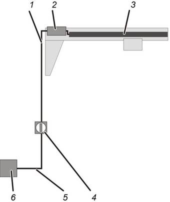
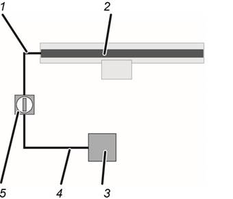
Only with single-rail
trolley tracks
Overview:
Electrical connection of the crane
─ The
power supply for the crane begins at the sub-distribution (3) of the mains
supply.
─ From
there, a line (4) runs to the mains switch (5) of the crane.
A mains switch is the best option for isolating the entire
crane.
The mains switch must be secured against inadvertent switching
back on.
The mains switch is usually located under the crane, e.g. on the
building wall or on a building support or concrete support.
─ From the
mains switch, the riser (1) extends to the crane.
─ There
the line is connected to the trolley power supply (2).
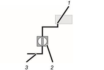
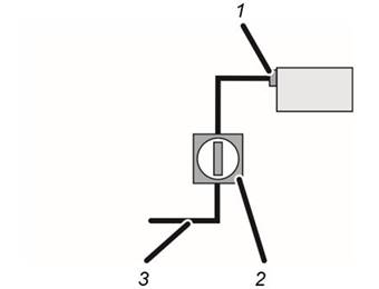
Only with solo chain
hoists
Overview:
Electrical connection of the crane
─ The
power supply for the solo chain hoist is connected according to the on-site
conditions in the building.
─ The line
(3) must have a mains switch as general mains switch for the entire crane
installation (2) or a plug-in connection as a mains disconnector plug.
The bayonet coupling (1) on the chain hoist cannot be secured
against switching back on and is therefore not suitable as a mains disconnector
plug.
Only with solo wire rope
hoists
Overview:
Electrical connection of the crane
─ The
power supply for the solo wire rope hoist is connected according to the on-site
conditions in the building.
─ The
mains disconnector plug (1) on the wire rope hoist can be secured against
inadvertent switching back on.
─ However,
it is still recommended that the line (3) have a mains switch as general mains
switch (2) for the entire crane installation.
Checking the
on-site mains supply
 For cranes without voltage
adapting transformer: Compare the operating voltage and mains frequency of the
crane with the mains voltage and frequency of the local mains supply.
For cranes without voltage
adapting transformer: Compare the operating voltage and mains frequency of the
crane with the mains voltage and frequency of the local mains supply.
The operating voltage and mains frequency are specified on the
type plates on the crane and in the test log book.
Operating voltage and mains voltage as well as mains frequency
must be matched for one another.
For cranes with voltage adapting
transformer: The mains voltage of the local mains supply must be converted to
the operating voltage of the crane by a voltage adapting transformer.
Compare the operating voltage and mains frequency at the input
of the voltage adapting transformer with the mains voltage and frequency of the
local mains supply.
Connecting the
crane
|

|
Danger to persons from electric shock!
There are high voltages when the crane is
connected.
This voltage could injure or kill people.
Work on electrical systems and components may only
be performed by a qualified electrician when the system is
voltage-free. |
Lay the lines, attach the mains
switch and connect the crane.
Checking the
rotary field
The crane may only be operated on a 3-phase mains supply with
a clockwise rotary field.
 Unlock the emergency stop
switch.
Unlock the emergency stop
switch.
Press the ‘Lift’ button
halfway.
● The load
hook must run slowly upward or remain stopped (if the top emergency limit switch
has already been triggered).
If the load hook travels downwards instead:
● The phases
in the mains supply have been interchanged.
Correct the interchanged
phases.
If possible, correct the phases at the point where they were
interchanged. Only in exceptional cases should the phases be interchanged again
directly on the power line.
Checking
protective conductors
All components of the crane are connected with the protective
conductor of the local mains supply. These connections are made through plug-in
connections, cable lugs and similar means.
For all protective conductor connections which have been
established during the assembly of the crane:
Carry out a visual inspection.
The protective conductors must be uninterrupted and correctly
connected.
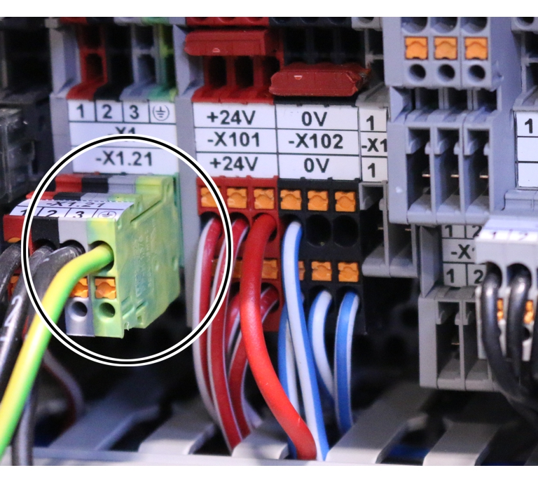
Examples of protective conductor connections:
Bush multipoint connector in prong terminal
block
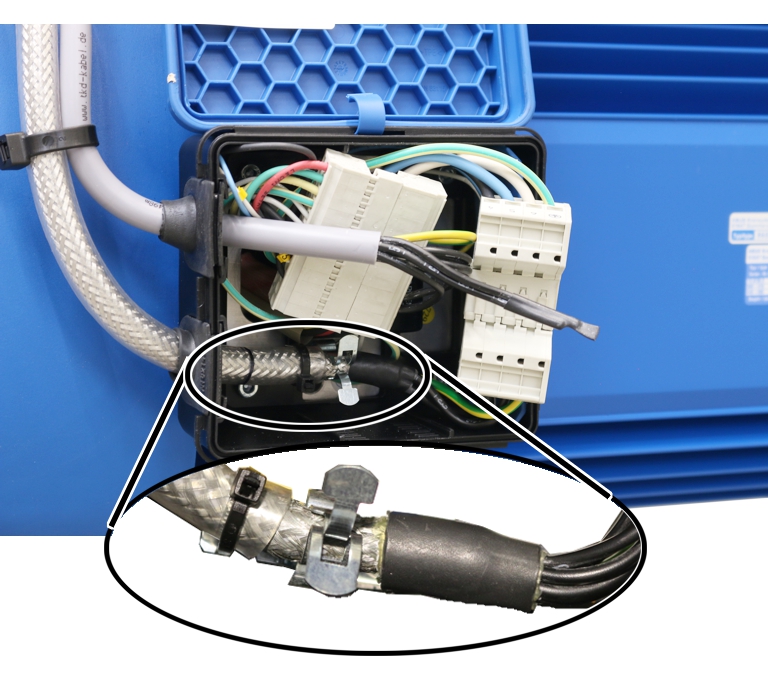
Screening clamp connection in connector housing
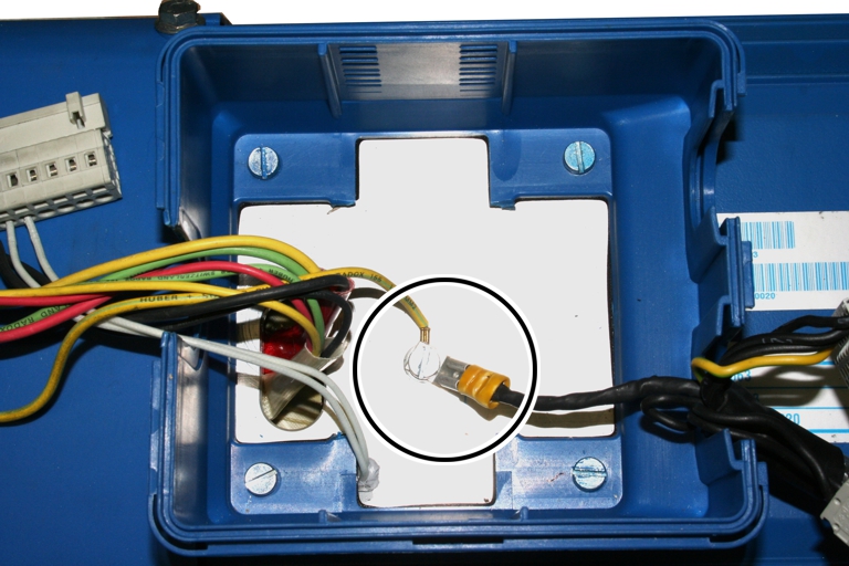
Cable lug in connector housing