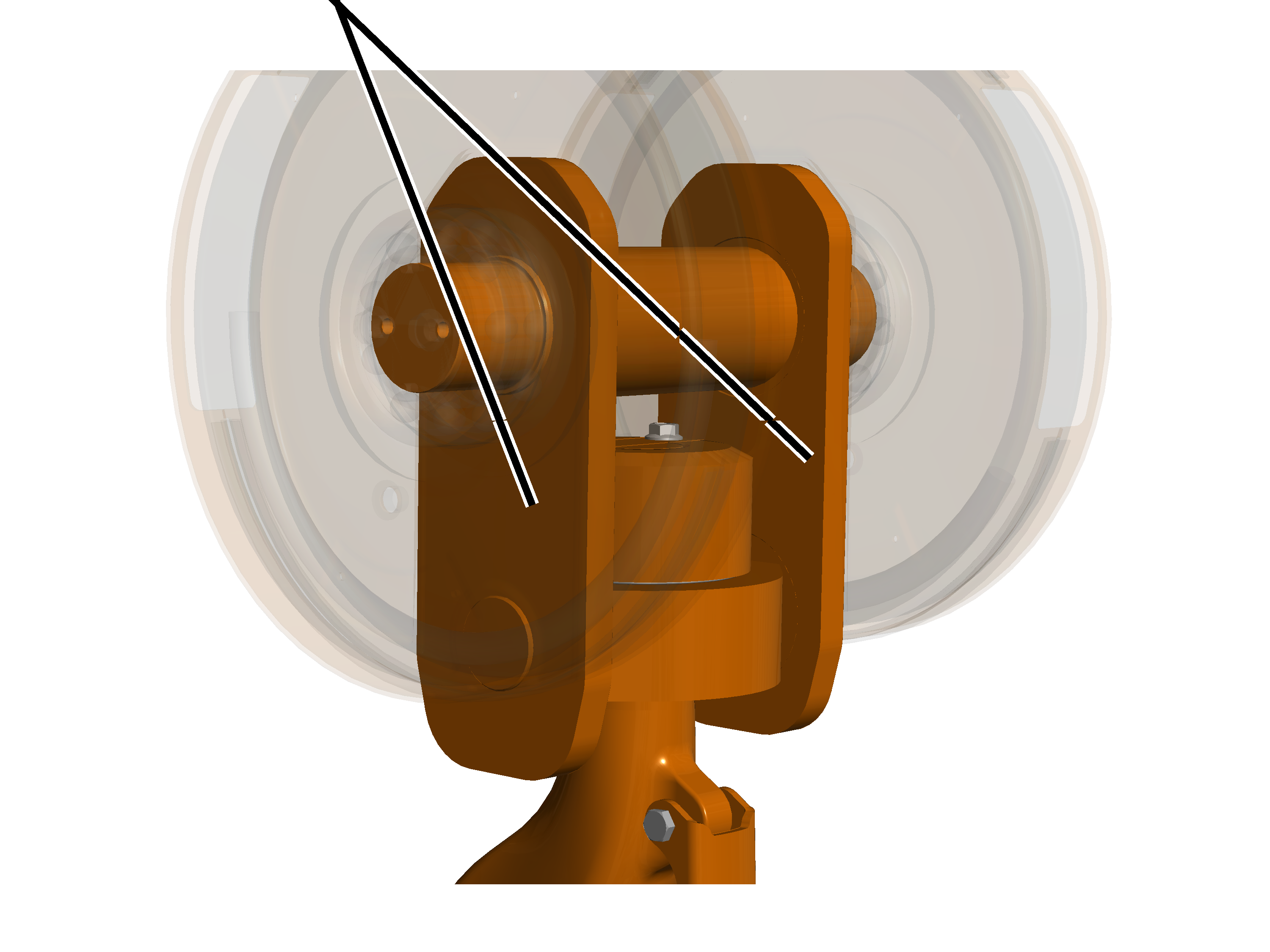
Only with wire rope
hoists
Checking for
ease of movement
|
|
Load
hook crosshead |
|
|
|
Load
hook |
|
 Rotate the load hook backwards
and forwards.
Rotate the load hook backwards
and forwards.
The load hook must be easy to move and freely rotatable.
Slew the load hook backwards and
forwards at the load hook crosshead.
The load hook crosshead must be freely slewable.
If the load hook is not easy to
move or freely rotatable or slewable, it must be repaired.
ABUS Service will gladly provide assistance if needed. See ABUS Service.
Inspecting the
bracket on the bottom block
|
Bracket |
|
|
|
 Inspect the brackets. They must
not exhibit any cracking, deformation or other signs of damage.
Inspect the brackets. They must
not exhibit any cracking, deformation or other signs of damage.
If the brackets are deformed or
damaged in any other way, they must be replaced.
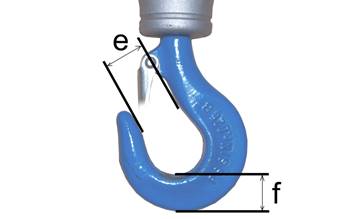
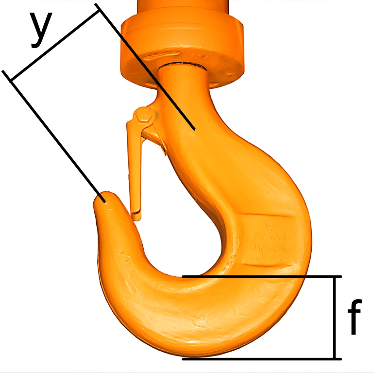
Measuring
deformation and wear of the load hook
Measure the distance ‘y’ between
the two stamped markings.
Read the reference distance for
‘y’ from the test log book or, if applicable, from the load hook itself.
The measured distance 'y' must not be greater than 1.1 times the
reference distance 'y'.
With ramshorn hooks, the distances 'y1' and 'y2' from the
engraved marking on the tip of the load hook to the marking on the shaft must
each be measured and compared separately.
Measure the base height 'f' of the load hook.
Compare the measured value with
the table.
The measured base height ‘f’ must not be smaller than given in
the table. The table specifies the minimum base height.
|
Size of load hook |
Type of load hook |
Min. base height 'f' [mm] |
|
1 |
Normal hook |
38 |
|
1.6 |
Normal hook |
45.6 |
|
2.5 |
Ramshorn hook |
47.5 |
|
2.5 |
Normal hook |
55.1 |
|
4 |
Ramshorn hook |
57 |
|
4 |
Normal hook |
63.7 |
|
6 |
Ramshorn hook |
71.3 |
|
6 |
Normal hook |
80.8 |
|
8 |
Ramshorn hook |
80.8 |
|
8 |
Normal hook |
90.3 |
|
10 |
Ramshorn hook |
90.3 |
|
10 |
Normal hook |
100.7 |
|
12 |
Ramshorn hook |
100.7 |
|
12 |
Normal hook |
112.1 |
|
16 |
Ramshorn hook |
112.1 |
|
16 |
Normal hook |
125.4 |
|
20 |
Ramshorn hook |
125.4 |
|
20 |
Normal hook |
142.5 |
|
25 |
Ramshorn hook |
142.5 |
|
25 |
Normal hook |
161.5 |
|
32 |
Ramshorn hook |
161.5 |
|
32 |
Normal hook |
180.5 |
|
40 |
Ramshorn hook |
180.5 |
|
40 |
Normal hook |
201.4 |
If the load hook has been
widened to a greater degree than is allowed or if the base height is below the
permissible limit, replace the load hook.
Do not carry out any repair welding (e.g. build-up welding) on
the load hook or on the load hook nut.
|
|
|
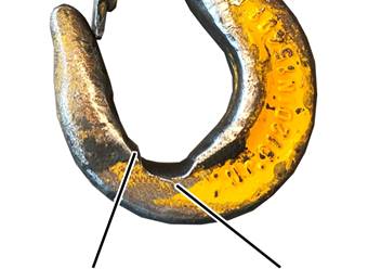
Edge at
transition to adjacent area in hook bed |
Protruding burr |
Check the wear surfaces in the
hook bed. They must merge gradually with the surrounding surfaces. They must not
have any sharp score marks and edges or other surface faults.
Inspect the edges. The side
edges on the hook should not have any exterior protruding burrs or similar
surface faults.
If the wear surfaces or side
edges do have sharp score marks or edges, these may be smoothed (e.g. filed).
The limit values for base height given above must be observed even after
smoothing.
Inspecting the
load hook surface
Inspect the load hook surface.
It must not have any faults, cracks or corrosion.
If the surface of the load hook
is to any extent not OK, disassemble the load hook and inspect the surface of
the hook shank. It must not have any faults, cracks or corrosion.
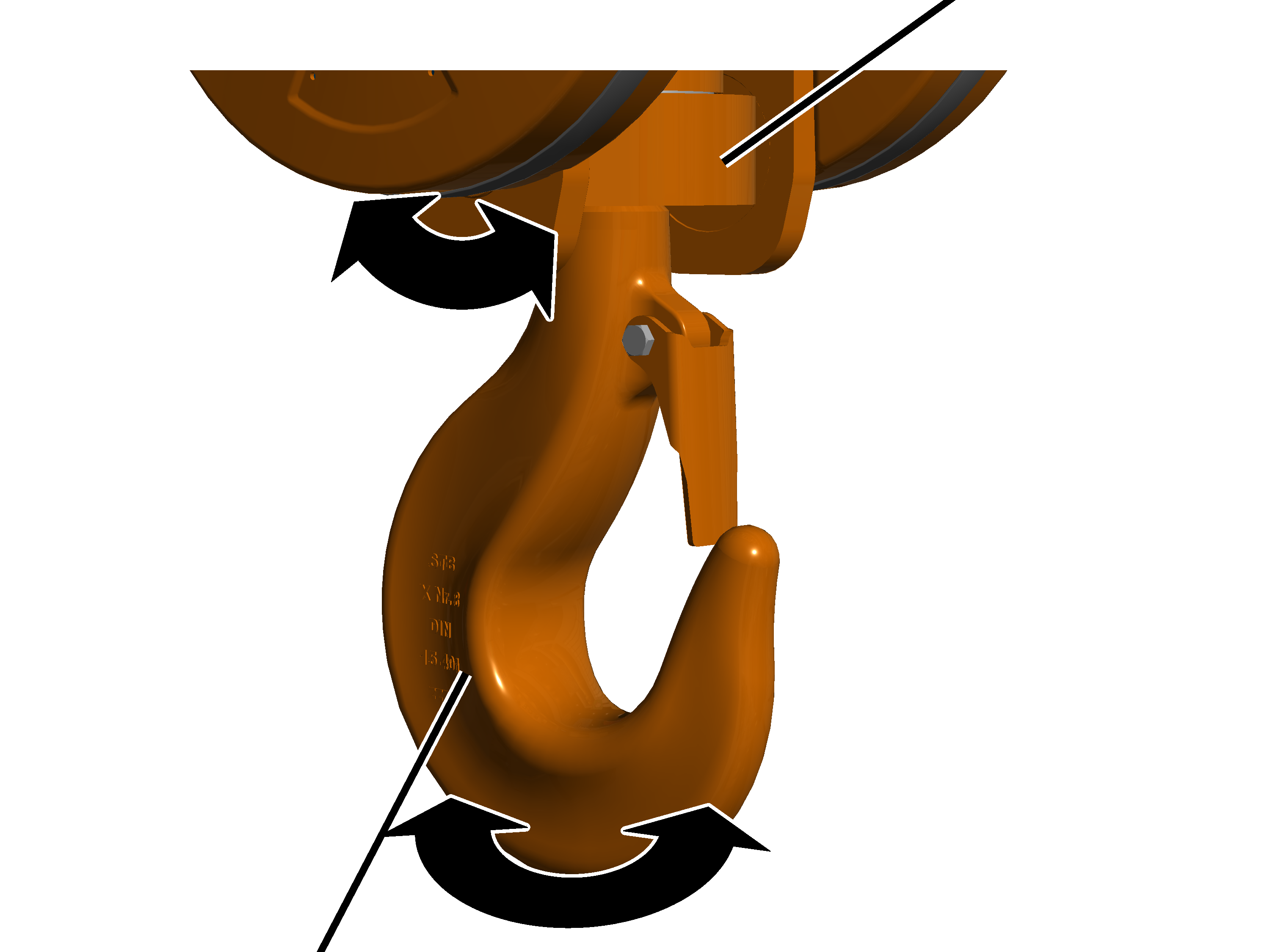
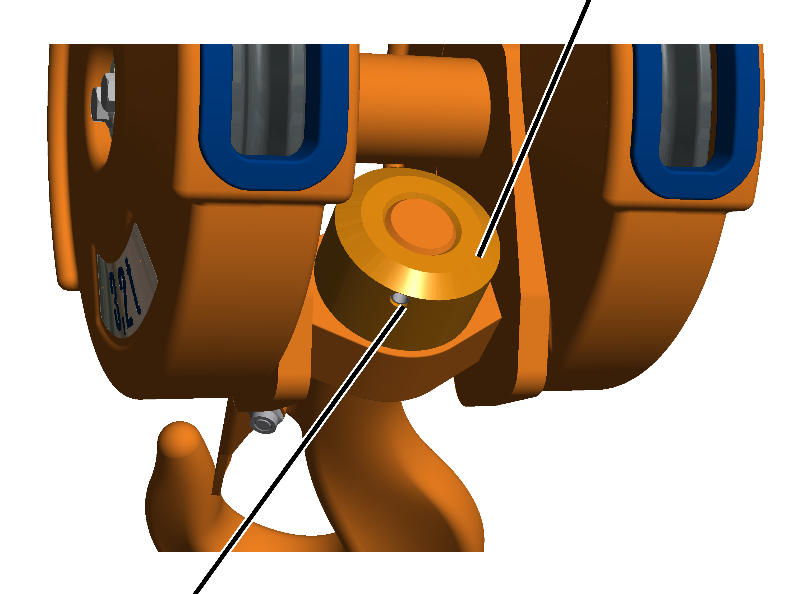
Inspecting the
anti-rotation device of the load hook nut
With load hooks with anti-rotation device through tensioner
sleeve:
|
|
Load
hook nut |
|
|
|
Tensioner sleeve |
|
Tilt the load hook until the
anti-rotation device is clearly visible.
Inspect the anti-rotation
device. The locking pin must be present, may not be damaged or broken and it
must sit securely.
If the locking pin is missing or
damaged, it must be replaced.
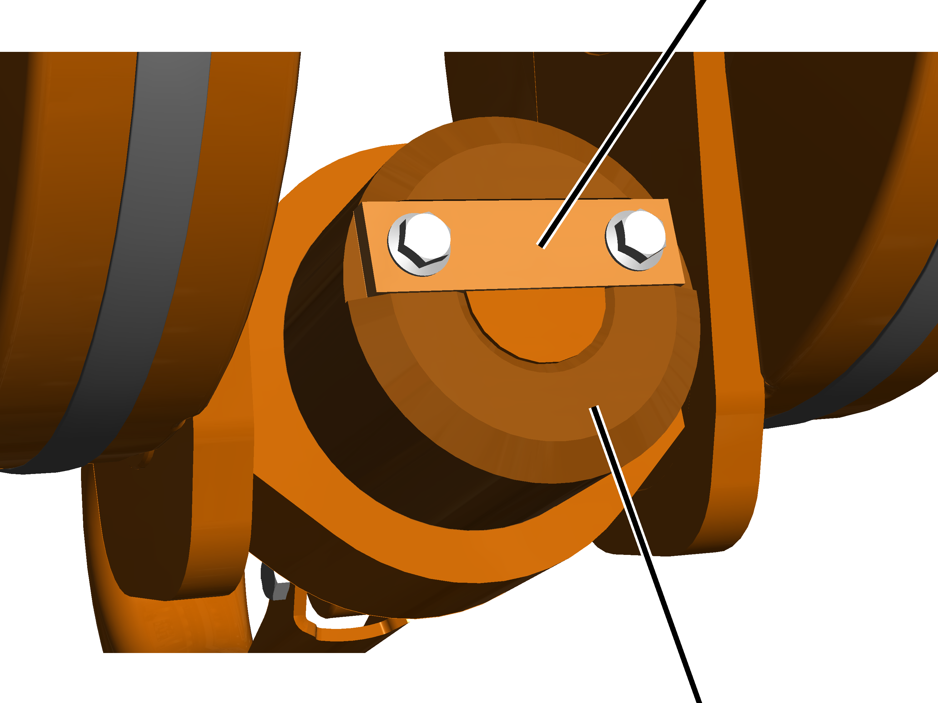
With load hooks with anti-rotation device through locking
plate:
|
|
Safety
plate |
|
|
|
|
Load
hook nut |
Tilt the load hook until the
anti-rotation device is clearly visible.
Inspect the anti-rotation
device. The safety plate must be present, undamaged and fit securely.
If the locking plate is missing
or damaged, it must be replaced.
Inspecting the
hook safety latch
|
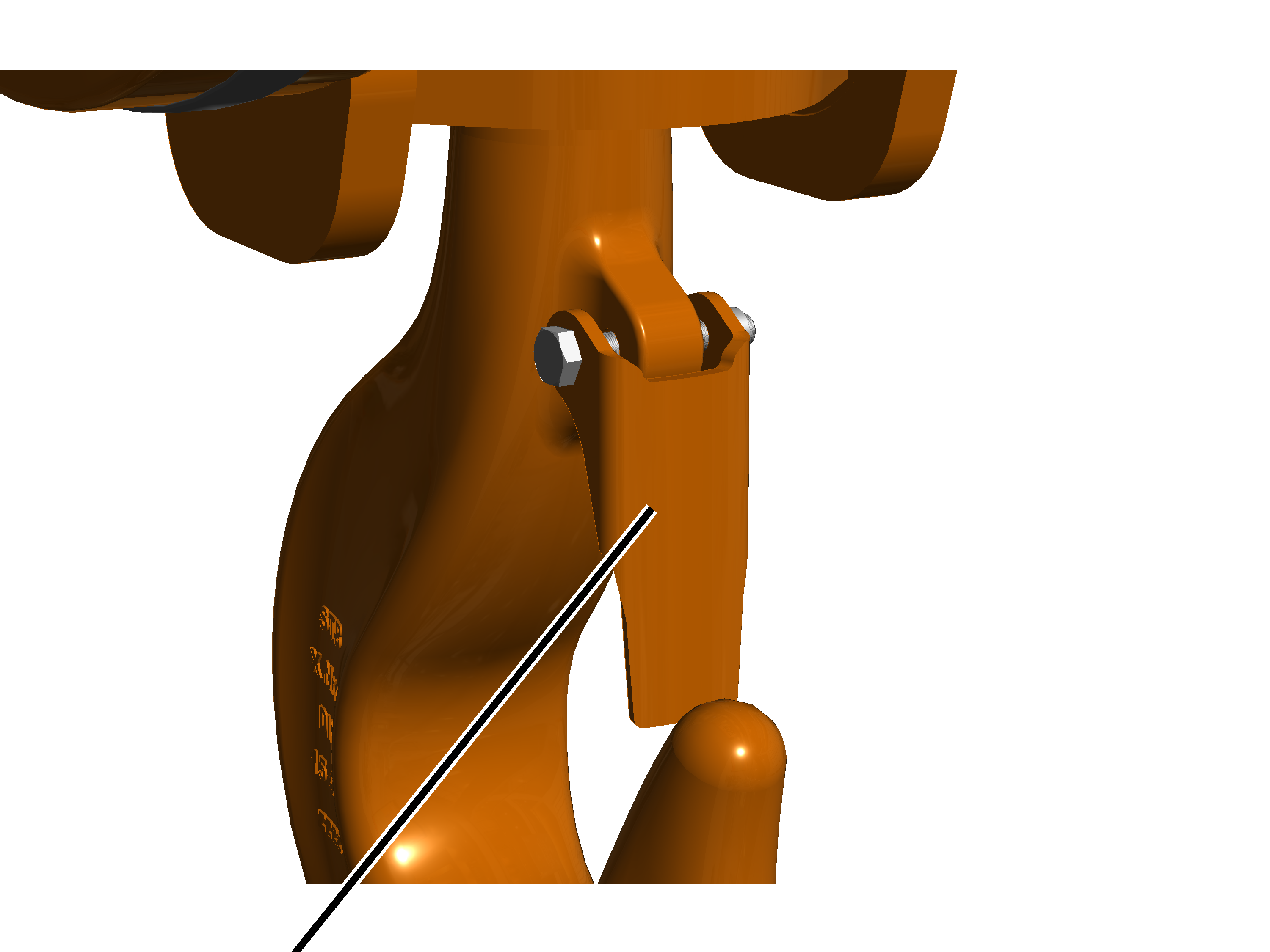
|
|
Hook
safety latch |
|
Inspect the hook safety latch.
It must be present, functional and easy to move, and must not be deformed or
damaged in any other way.
If the hook safety latch is
missing, damaged or not working properly, it must be replaced.