If the drive is to be connected to an installation not manufactured by ABUS, continue reading. If the drive is to be connected to an ABUS crane installation, see Connecting the drive to an ABUS crane.
─ The drive is connected in the connector housing on the drive using a plug-in connection.
The plug-in connection is available as a set, AN 105581.
─ When connecting, ensure that the rectifier for the brake is provided with alternating current in the connector housing with the drive switched on. This will require a jumper in the circuitry.
─ The drive can be connected three ways: pole-changeable (high and low speeds), with only one of the two speeds, and through a frequency converter.
─ The drive cannot be operated in a delta connection.
─ Heed the duty cycle of the drives for high and low travel speed.
|
|
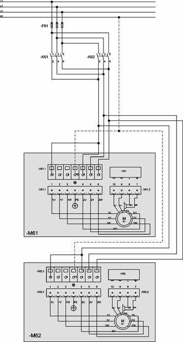
M61: Crane drive 1, M62: Crane drive 2, V61 and V62: Rectifier, U61: Smooth switching relay, K63: Contactor for high speed, K62: Contactor for crane travel forward, K61: Contactor for crane travel backward
 Connect the protective
conductors to both drives.
Connect the protective
conductors to both drives.
Connect contacts 1, 2 and 3 for
low speed.
Connect contacts 4, 5 and 6 for
high speed.
When switching from low to high
speed (contactor K63) plan a delay of 0.5 seconds in the circuit. The drive is thereby prevented from running in a starting
current for a longer period in inching mode (rapid switching back and forth).
This would eventually damage the motor.
 To
prevent excessive swinging of the load during braking from high speed to low
speed, include the SU1 device. When braking from
high to low speed, only two of the three phases of the drive are briefly
switched to low speed. In doing so, the drive does not jerk to a halt but brakes
softly.
To
prevent excessive swinging of the load during braking from high speed to low
speed, include the SU1 device. When braking from
high to low speed, only two of the three phases of the drive are briefly
switched to low speed. In doing so, the drive does not jerk to a halt but brakes
softly.
When low speed is switched
(contactor K 63 not switched) always switch a single phase of the high speed as
well (contact 6). Otherwise there will be no voltage between the star points of
the high speed and the low speed and the brake will not be aerated.
|
|
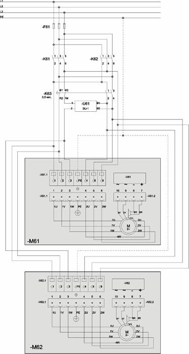
M61: Crane drive 1, M62: Crane drive 2, V61 and V62: Rectifier, K62: Contactor for crane travel forward, K61: Contactor for crane travel backward
Connect the protective
conductors to both drives.
Connect contacts 4, 5 and 6 for
high speed.
When high speed only is
switched, always switch a single phase of the low speed as well (contact 1).
Otherwise there will be no voltage between the star points of the high speed and
the low speed and the brake will not be aerated.
When switching the drive to high
speed (from standstill), allow the drive to run at low speed for 0.5 seconds
first. The delay avoids the drive running in a starting current for a longer
period during switch-on. This would eventually damage the drive.
Connect the protective
conductors to both drives.
Connect contacts 1, 2 and 3 for
low speed.
When low speed only is switched,
always switch a single phase of the high speed as well (contact 6). Otherwise
there will be no voltage between the star points of the high speed and the low
speed and the brake will not be aerated.
|
|
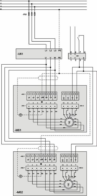
M61: Crane drive 1, M62: Crane drive 2, V61: Rectifier, U61: Frequency converter
Connect the shields for the
connection cables to the protective conductor on the drive.
Only use shielded connection cables for the drives.
Connect the protective
conductors to both drives.
Connect contacts 4, 5 and 6.
Connect contacts 7 and 8 for the
brake control. The electrical circuit must be open at a frequency of
0 Hz.
Brake performance data: 195 Volt DC, 50 Watt.