Compare the operating voltage
and frequency range on the type plate with the mains voltage and frequency of
the local grid.
Compare the operating voltage
and frequency range on the type plate with the mains voltage and frequency of
the local grid.
If the drive is to be connected to an ABUS crane installation, read on for further instructions. If the drive is to be connected to a different installation: see Connecting the drive to crane installations not made by ABUS.
Compare the operating voltage
and frequency range on the type plate with the mains voltage and frequency of
the local grid.
|
|
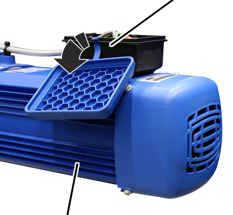
Connector housing |
|
| |
|
Drive |
|
 Open the housing cover.
|
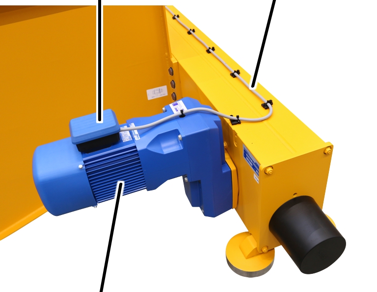
Connector housing |
Connection cable |
|
| |
|
Drive |
|
Lay the connection cable for the
drive.
Lay the connection cable in the
connector housing.
|
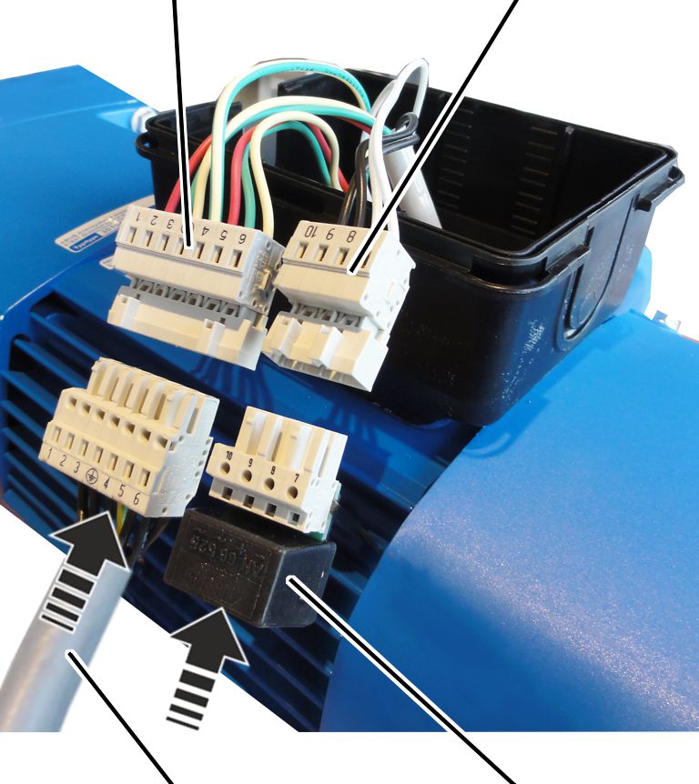
Pin
multipoint connector |
Pin
multipoint connector |
|
| |
|
Connection cable of drive |
Rectifier for brake |
Insert the connection cable for the drive in
the pin multipoint connector on the drive.
Insert the rectifier for the
brake in the pin multipoint connector on the drive.
Lay the plug-in connections and
connection cable in the connector housing.
|
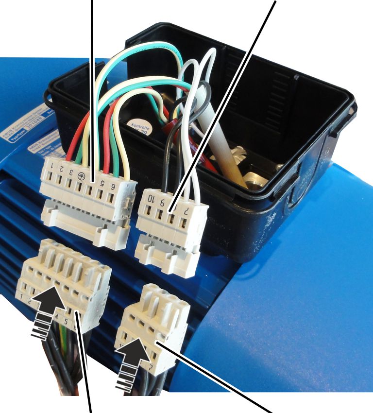
Pin
multipoint connector | |
|
| |
|
Bush multipoint connector for drive |
Bush multipoint connector for brake |
Insert the bush multipoint connector for the
drive on the pin multipoint connector on the drive.
Insert the bush multipoint
connector for the brake on the pin multipoint connector on the drive.
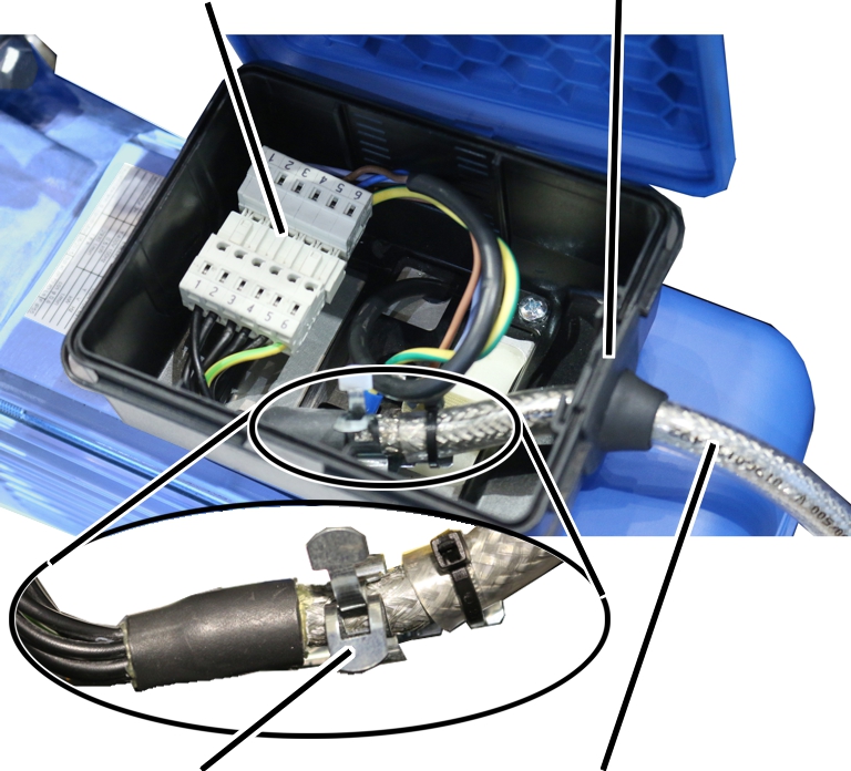
|
Plug-in connection |
Cable bushing |
|
| |
|
Screening clamp connection |
Connection cable |
Fasten the connection cable to
the screening clamp connection using cable ties.
Lay the plug-in connections and connection
cable in the connector housing.