Prior to installation, plan
where and how to install the receiver on the crane.
Prior to installation, plan
where and how to install the receiver on the crane.
Prior to installation, plan
where and how to install the receiver on the crane.
For a wireless connection that is as stable as possible:
─ The receiver must be positioned so that it can transmit freely in all directions. The receiver may therefore not be blocked by metal parts in its direct vicinity.
─ The minimum clearance between the receiver and metal parts in any direction is 1 m.
─ Plan the position of the receiver so that it can be connected to the crane panel using the connection cable supplied.
─ The receiver must be positioned vertically and the connection cable must be guided downward out of the receiver.
─ The receiver must be positioned so that the LEDs point toward the midpoint of the crane and are easy to read in the operating range of the crane.
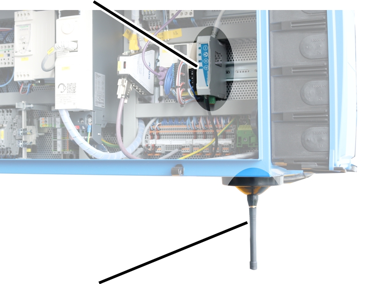
Example for the installation of the CAN bus receiver:
|
CAN bus receiver |
|
|
| |
|
Magnetic base antenna |
|
─ The CAN bus receiver is installed in the crane panel. To provide a wireless connection that is as stable as possible, an external magnetic base antenna is connected and guided out of the crane panel.
─ The instructions stated above apply to the installation of the magnetic base antenna.
─ Attach the magnetic base antenna so that nothing becomes caught during crane travel or trolley travel.
|
|
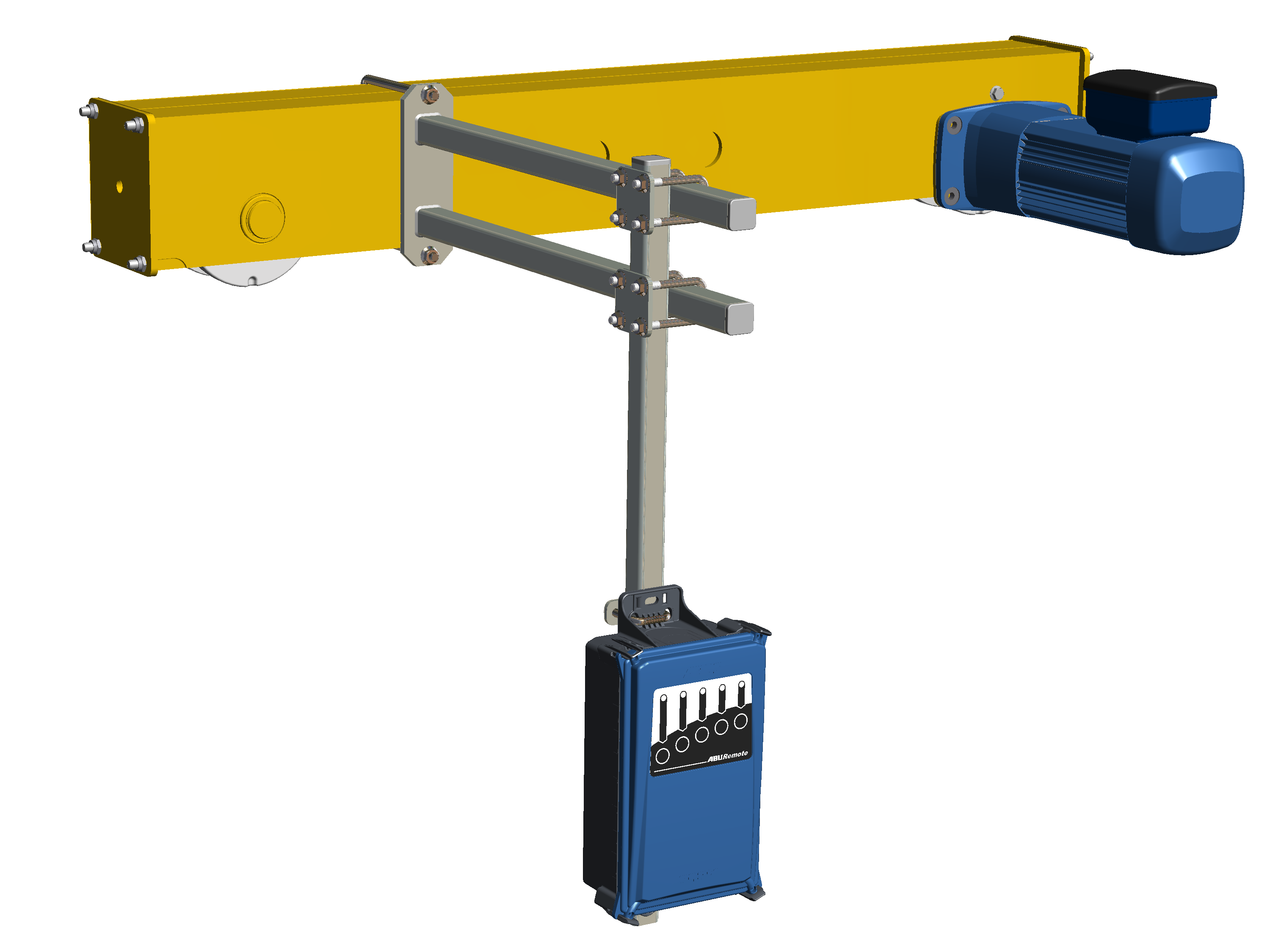
─ Single girder travelling crane: The receiver should be fastened on the end carriage as shown in the illustration. The receiver should protrude downward under the main girder in order to be able to transmit freely in all directions.
─ Double girder travelling crane: The receiver should be fastened between the two main girders as shown in the illustration. The receiver should protrude downward under the main girders in order to be able to transmit freely in all directions.
─ Wall travelling crane: The receiver should be fastened on the middle end carriage as shown in the illustration. The receiver should hang at about the height of the lower end carriage of the wall travelling crane.
|
|
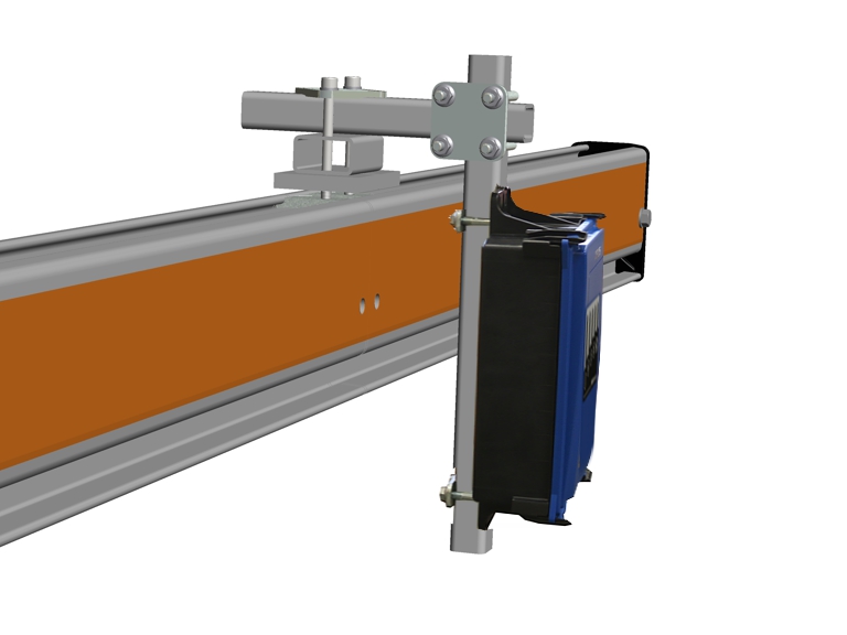
─ HB system: The receiver should be fastened as shown in the illustration with a clamping unit in the profile head on the crane girder.
|
|
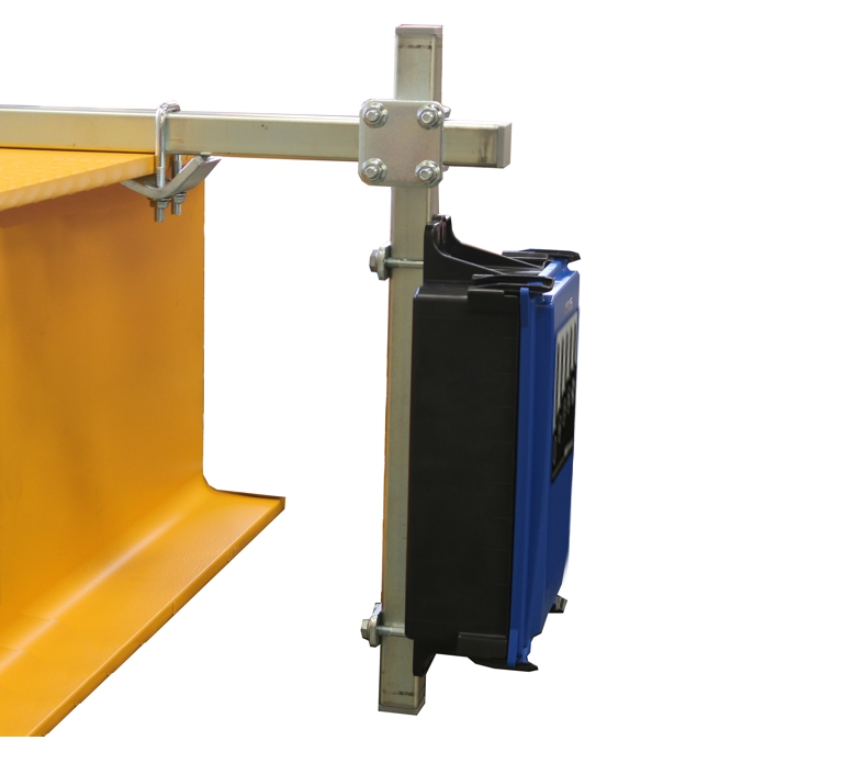
─ Underslung travelling crane: The receiver should be fastened as shown in the illustration with clamping claws on the upper flange on the main girder.
─ Jib crane: The receiver should be fastened as shown in the illustration with clamping claws on the upper flange on the jib arm.