Lower the load hook to the
desired lowest hook position.
Lower the load hook to the
desired lowest hook position.
Lower the load hook to the
desired lowest hook position.
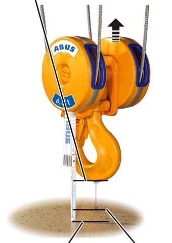
─ The load hook should not touch the floor of the building.
─ The wire rope should not be slack.
─ A certain minimum clearance must be maintained between the cable guide and the drum housing. This clearance is determined in the next work step.
─ The hook path (distance between the highest hook position (= hook headroom, C-size) and the lowest hook position) must not be greater than is specified on the type plate.
|
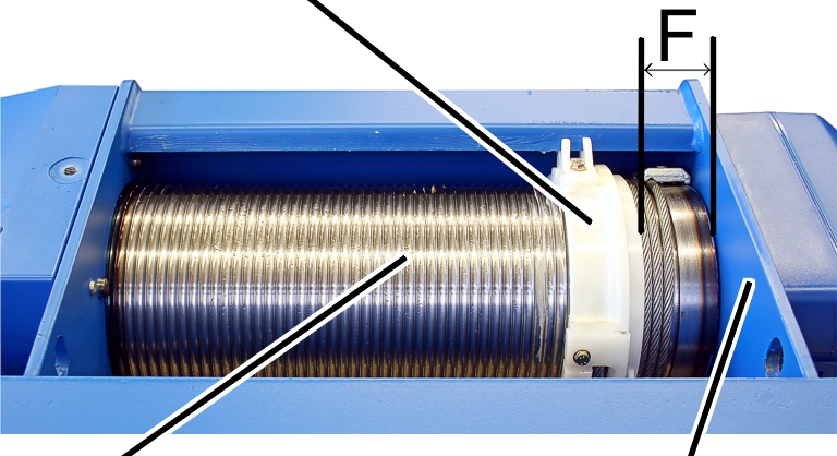
Cable guide |
|
|
| |
|
Cable drum |
Drum housing |
Measure the distance 'F'
between the cable guide and the drum housing and compare this with the
table.
|
Wire rope hoist |
Type |
Reeving |
Spacing 'F' [mm] |
|
GM 800 |
E, D, DA |
4/1 |
42 ± 2 |
|
GM 1000 |
E, D, |
4/1 2/1 |
56 ± 2 |
|
GM 2000 |
E, D, |
4/1 2/1 |
59 ± 2.5 |
|
GM 3000 |
E, D, |
4/1 2/1 |
73 ± 2.5 |
|
GM 5000 |
E, D, DA, DQA |
4/1 2/1 |
87.5 ± 3 |
|
GM 5000 |
D |
4/2 |
73 ± 2.5 |
|
GM 5000 |
Z |
4/2 8/2 |
87.5 ± 3 |
|
GM 6000 |
E, D, DA, DQA |
4/1 2/1 |
102 ± 3 |
|
GM 6000 |
Z |
4/2 8/2 |
102 ± 3 |
|
GM 7000 |
D, DA, |
2/1 4/1 6/1 |
131 ± 4 |
|
GM 7000 |
D |
4/2 8/2 |
87 ± 3 |
|
GM 7000 |
Z, ZA |
4/2 6/2 8/2 10/2 |
131 ± 4 |
|
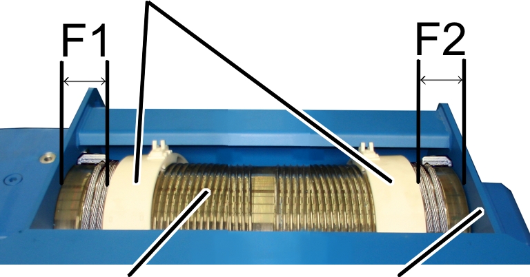
Cable guide |
|
|
| |
|
Cable drum |
Drum housing |
Measure the distances 'F1'
and ‘F2’ between the cable guides and the drum housing and compare these with
the table.
|
Wire rope hoist |
Spacing 'F1' [mm] |
Spacing 'F2' [mm] |
|
GM 3000 - D |
66 ± 3 |
66 ± 3 |
|
GM 5000 - D |
80 ± 3 |
76 ± 3 |
|
GM 7000 - D |
84 ± 3 |
87 ± 3 |
|
|
Danger from falling suspended load! The cable can be torn from the cable drum, causing the suspended load to fall and kill or injure people if the distances ‘F’ or ‘F1’ and ‘F2’ are not heeded. These distances guarantee that there is always enough wire rope wound onto the cable drum. Always maintain ‘F’ or ‘F1’ and ‘F2’. |
If necessary, raise the
load hook until the distance 'F' or ‘F1’ or ‘F2’ is achieved.
● The lowest hook position of the load hook has now been determined.
This working step only applies if the bottom hoist limiter may be travelled to during normal operation.
The gear limit switch has a fourth switching point. This is used as backup limiter underneath the bottom hoist limiter.
At the lowest hook position previously travelled to:
|
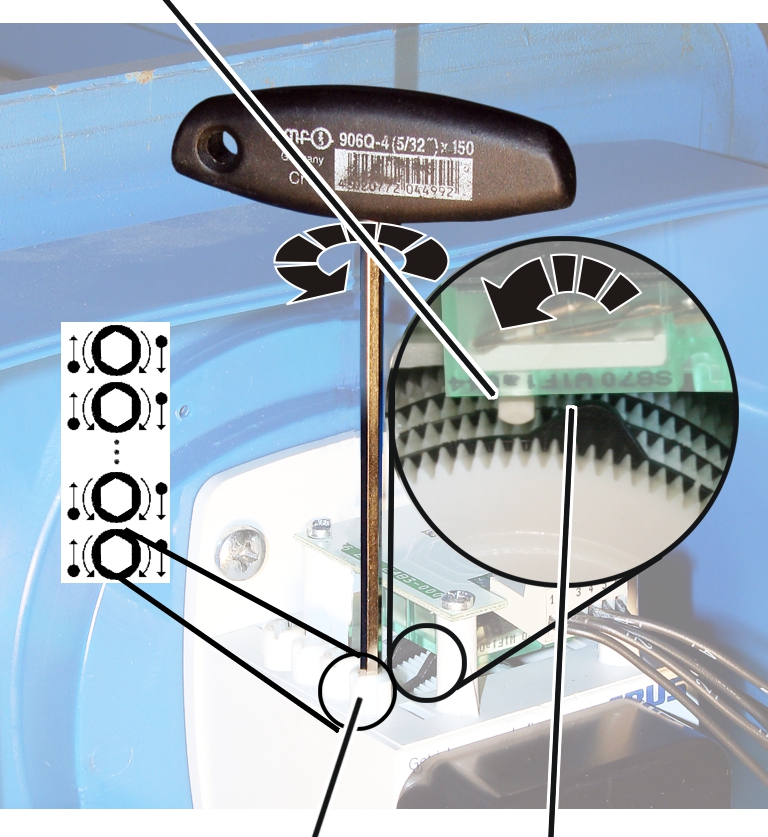
Control cam |
| |
|
| ||
|
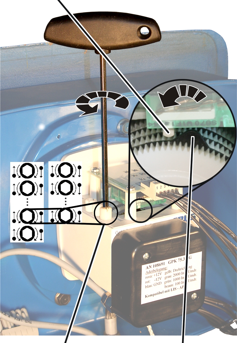
Adjusting screw |
Microswitch | |
─ The backup limiter for the bottom hoist limiter is set using the foremost white adjusting screw. The gear limit switch has at least four switching points.
 If necessary: Turn the
adjusting screw until the control cam is to the right of the microswitch. It
should not be either directly on or to the left of the microswitch.
If necessary: Turn the
adjusting screw until the control cam is to the right of the microswitch. It
should not be either directly on or to the left of the microswitch.
Turn the adjusting screw
to the left until the control cam presses in an anti-clockwise direction against
the microswitch and an audible click is heard.
● The main contactor switches off.
If the switching point is set with a different adjusting screw than previously specified, this is noted on the wiring diagram.
|
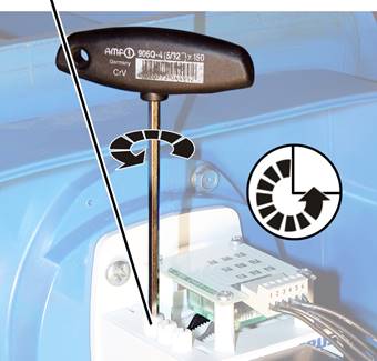
Adjusting screw |
|
|
| |
Turn the adjusting screw
three-quarters of a turn to the right.
● The microswitch switches again; the main contactor switches back on.
Raise the load hook
slightly.
Turn the adjusting screw
three-quarters of a turn back to the left.
Read off the braking
distance from the table.
This braking distance is determined by the LIS-SV and is not identical to the braking distance during lifting/lowering in normal crane operation.
|
|
Lifting speed 3000 rpm |
Lifting speed 6000 rpm |
|
Reeving |
320 mm |
1280 mm |
|
Reeving |
160 mm |
640 mm |
|
Reeving |
106 mm |
480 mm |
|
Reeving |
128 mm |
512 mm |
|
Reeving |
213 mm |
853 mm |
|
Lowest
hook |
|
|
| |
|
Floor of building |
Lowest hook position |
Raise the load hook until
it is exactly at the braking distance to the lowest hook position.
At the lowest hook position with braking distance previously travelled to:
|
Microswitch |
| |
|
| ||
|
Adjusting screw |
Control cam | |
─ With gear limit switch with three switching points: The bottom hoist limiter is set using the foremost white adjusting screw.
─ With gear limit switch with more than three switching points, where additional switching points are provided in the traversing range of the load hook: The bottom hoist limiter is set using the foremost white adjusting screw.
─ During normal operative travel of the bottom hoist limiter: The bottom hoist limiter is set using the second white adjusting screw from the front.
If necessary: Turn the
adjusting screw until the control cam is to the right of the microswitch. It
should not be either directly on or to the left of the microswitch.
Turn the adjusting screw
to the left until the control cam presses in an anti-clockwise direction against
the microswitch and an audible click is heard.
If the switching point is set with a different adjusting screw than previously specified, this is noted on the wiring diagram.
Raise the load hook.
Lower the load hook at
both slow and fast lifting speed and check whether it halts at the lowest hook
position.
|
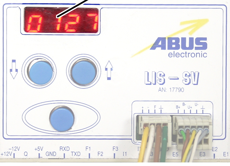
Display of impulses |
|
|
| |
● The counted impulses of the encoder are shown in the LIS-SV display.