Top hoist limiter
Bottom hoist limiter
The ABULiner Lifting/Lowering unit:
─ The ABULiner enables continuous control of the lifting speed of wire rope hoists.
─ For the control, a conventional pendant control with two-stage buttons or a radio remote control device is used.
─ Only for double lifting speed: The ABULiner enables a maximum lifting speed of up to 3000 rpm in the standard version. The lifting speed can be optionally increased up to 6000 rpm (= doubled). This means that the crane can be worked faster. The maximum possible additional lifting speed (above 3000 rpm) depends on the suspended load.
─ Only for auxiliary fans: The hoist motor is equipped with an auxiliary fan (option). The auxiliary fan continues to run for several minutes after the lifting or lowering.
For single-winding hoist drives that are not pole-switchable, (e.g. GM 800 und GM1000 modular und GM7000.2), the speed of the hoist motor is monitored by the frequency converter using a separate absolute rotary encoder, thus also enabling full torque at very slow lifting speeds so that the load can be held until a standstill is reached even without braking.
Frequency converter:
─ The frequency converter thus saves wear on the mechanical disc brake by braking with the hoist motor.
─ The frequency converter is specifically programmed for the particular job and adapted to the exact technical data of the hoist motor and the conditions within the building.
─ Only with ABULiner with power feedback unit: The frequency converter feeds electrical energy back into the mains supply. This energy arises from the regenerative braking of the hoist motor and is then conveyed back through the frequency converter to the mains supply.
This saves energy, since the energy is not fed into a braking resistance as is usually the case, where it would have to be transformed into heat.
In a frequency converter with energy recovery ability, no mains choke is necessary.
Only with Schneider ABULiner: The power feedback unit has a modular design and consists of one or several modules, depending on the power.
─ Only with ABULiner Lifting/Lowering with Schneider frequency converter and ABULiner trolley travel: The frequency converters are coupled together. The frequency converter for trolley travel draws its energy from the frequency converter for lifting/lowering.
Control unit:
─ In order to operate a crane with the ABULiner, a control unit is required.
─ The control unit switches the control signals from the pendant control or the receiver of the radio remote control and from the LIS-SV electrically isolated to the inputs of the frequency converter.
─ It also switches the brake of the hoist motor.
─ The control unit enables troubleshooting by means of light diodes for the control signals from the LIS-SV.
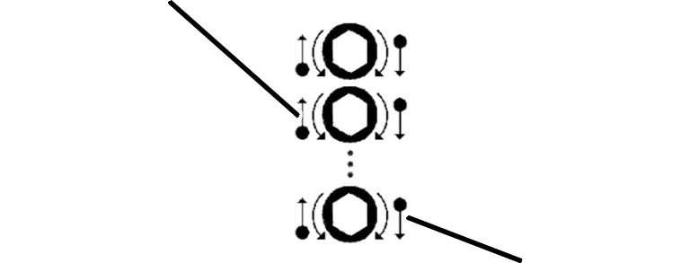
─ The encoder is directly mounted on the gear limit switch.
─ It consists of a rotary disc with 2000 markings around the circumference, which are electronically counted.
─ Together with the LIS-SV, the encoder monitors the rotational direction and rotational speed of the cable drum. This is then compared with the set values of the frequency converter. If the cable drum rotates 20% faster than the set value or in the wrong direction, the crane's main contactor is switched off immediately for reasons of safety and the hoist motor is braked.
─ The encoder forwards the position of the cable drum to the LIS-SV with 2000 impulses per rotation. This thus enables an exact positioning of the highest and lowest hook setting.
─ The LIS-SV monitors the entire ABULiner system for proper functioning.
─ The LIS-SV calculates the lifting speed and rotational direction from the signal of the encoder.
─ The LIS-SV is fully integrated in the ABULiner.
─ The LIS-SV evaluates the control signals of the pendant control or the radio remote control and the encoder and switches the inputs of the control unit.
─ The LIS-SV determines the weight of the suspended load and switches the hoist motor off if overloaded.
─ The LIS-SV can detect if a load is lifted with a jerking motion. In this case, the lifting speed is reduced to about 15 Hz until the fast increase in load has stopped.
─ Only for auxiliary fans: The LIS-SV controls how many minutes the auxiliary fan of the hoist motor continues running.
─ Only for doubled lifting speed: The LIS-SV measures the mass of the suspended load and calculates the maximum speed with which the crane may lift (in the range from 3000 rpm to 6000 rpm) in order to apply the required torque for the load.
|
Top hoist limiter |
|
|
| |
|
|
Bottom hoist limiter |
─ The wire rope hoist has a geared limit switch that functions as a hoist limiter. It is directly coupled with the cable drum. It ensures that the load hook does not travel farther than the highest or the lowest hook position.
─ The upper switching point is called "top hoist limiter" (second white adjusting screw from the back), the lower switching point is called "bottom hoist limiter" (foremost white adjusting screw).
─ If the load hook reaches the switching point of the hoist limiter, the frequency converter, which is controlled by the LIS-SV, slowly brakes the hoist motor. The switching points must not be deliberately triggered during the normal course of work.
─ Additional switching points can be located between the two hoist limiters and used for special switching circumstances.
─ Only for gear limit switches with additional black adjusting screw: All the switching points can be moved together with the black adjusting screw.
|
Backup limiter |
|
|
─ The gear limit switch has another switching point as standard. It is called the backup limiter (backmost white adjusting screw). It is located above the top hoist limiter.
─ If the top hoist limiter is no longer working (e.g. through faulty contactors, inversely poled rotary field, etc.) and the load hook thus moves above the switching point of the top hoist limiter, the backup limiter switches off the main contactor and thus the whole crane.
─ The backup limiter has been set in the factory and sealed.
Normal operative travel
─ Normally the switching points of the top and bottom hoist limiter must not be travelled to during normal operation (during the normal workflow) since the microswitches of the hoist limiters could become worn by regular use.
─ If the switching points are travelled to during normal operation, there must be an additional backup limiter available which ensures safe switch-off if a hoist limiter microswitch is worn. This backup limiter must be able to be checked regularly.
─ Backup limiter for the top hoist limiter: The top hoist limiter has a backup limiter as standard. If the top hoist limiter is travelled to during normal operation, there is a toggle switch on the wire rope hoist which can be used to bypass the top hoist limiter for the backup limiter to be checked.
─ Backup limiter for the bottom hoist limiter: If the bottom hoist limiter is travelled to during normal operation, a gear limit switch with at least four switching points is used. This fourth switching point is used as backup limiter underneath the hoist limiter. In addition, there is a toggle switch on the wire rope hoist which can be used to bypass the bottom hoist limiter for the backup limiter to be checked.
|
|
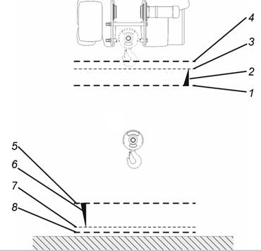
Top hoist limiter:
─ 1: Switching point of the top hoist limiter. If it is triggered, the LIS-SV starts with the load hook brake phase.
─ 2. The load hook brakes, determined by the LIS-SV.
─ 3: The load hook comes to a standstill just before the backup limiter.
─ 4: Switching point of the backup limiter. If it is triggered (e.g. because the microswitch of the top hoist limiter is worn), the gear limit switch switches off the main contactor and thus the whole crane.
If the top hoist limiter is travelled to during normal operation, there is a toggle switch on the wire rope hoist which can be used to bypass the top hoist limiter for the backup limiter to be checked.
Bottom hoist limiter:
─ 5: Switching point of the bottom hoist limiter. If it is triggered, the LIS-SV starts with the load hook brake phase.
─ 6. The load hook brakes, determined by the LIS-SV.
─ 7: The load hook comes to a standstill shortly before the lowest hook position (e.g. floor of building).
─ 8. If the bottom hoist limiter is travelled to during normal operation, a gear limit switch with at least four switching points is used. This fourth switching point is used as backup limiter underneath the hoist limiter. In addition, there is a toggle switch on the wire rope hoist which can be used to bypass the bottom hoist limiter for the backup limiter to be checked.