Description of the
device
The ABULiner
Lifting/Lowering unit consists of:
─
Frequency converter U21
─ Control
unit U22
─
Encoder
─
LIS-SV
Overall view of
panel:
Depending on the variant, the frequency converter/s is/are
located at different positions and/or in different panels. The following figure
can be used as a guide.
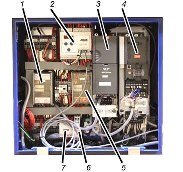
Only with Danfoss frequency
converter
Hoist panel:
─ 1:
Control unit for ABULiner Trolley Travel System (U42)
See product manual “ABULiner Crane/Trolley Travel System”
─ 2:
LIS-SV
─ 3:
Frequency converter for ABULiner Trolley Travel System (U41)
See product manual “ABULiner Crane/Trolley Travel System”
─ 4:
Frequency converter for ABULiner Lifting/Lowering (U21)
─ 5:
Control unit for ABULiner Lifting/Lowering (U22)
─ 6:
Rectifier
─ 7: Brake
contactor (K26.3)
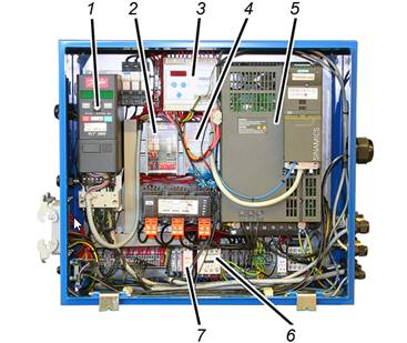
Only with Siemens frequency
converter
Hoist panel:
─ 1:
Frequency converter for ABULiner Trolley Travel System (U41)
See product manual “ABULiner Crane/Trolley Travel System”
─ 2:
Control unit for ABULiner Trolley Travel System (U42)
See product manual “ABULiner Crane/Trolley Travel System”
─ 3:
LIS-SV
─ 4:
Control unit for ABULiner Lifting/Lowering (U22)
─ 5:
Frequency converter for ABULiner Lifting/Lowering (U21)
─ 6: Brake
contactor (K26.3)
─ 7:
Rectifier
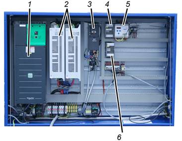
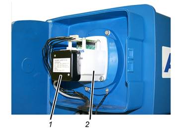
Only with the Schneider
frequency converter
Hoist panel:
─ 1:
Frequency converter for ABULiner Lifting/Lowering (U21)
─ 2: Power
feedback unit (option)
─ 3:
Frequency converter for ABULiner Trolley Travel System (U41)
See product manual “ABULiner Crane/Trolley Travel System”
─ 4:
Control unit for ABULiner Lifting/Lowering (U22)
─ 5:
LIS-SV
─ 6:
Control unit for ABULiner Trolley Travel System (U42)
See product manual “ABULiner Crane/Trolley Travel System”
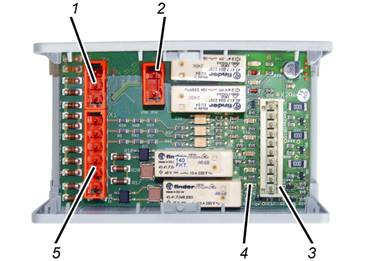
Control unit for ABULiner Lifting/Lowering:
─ 1: Pin
multipoint connector X4
─ 2: Pin
multipoint connector X3
─ 3: Pin
multipoint connector X2
─ 4:
LED
─ 5: Pin
multipoint connector X1
Encoder:
─ 1:
Encoder
─ 2: Gear
limit switch