Log in to KranOS with user
"Service" (user level [1]) or "Abnahme" (commissioning) (user level [2]). See
Connecting laptop or
tablet computer with ABUControl.
Log in to KranOS with user
"Service" (user level [1]) or "Abnahme" (commissioning) (user level [2]). See
Connecting laptop or
tablet computer with ABUControl.Additional functions can be switched on the crane via load-controlled switching points. Outputs on the crane control can be used for this, which switch as soon as more than a certain load is lifted by the crane.
For the crane (total load) and for each hoist, up to two load-controlled switching points are available. The planning and electrical connection of the outputs is done according to the specific order. The setting of the loads for each switching point is performed in KranOS.
Two example applications for this function could be signal lamps (for example, under 85% of the maximum load capacity a green signal lamp lights up), or the control of a gripper (from 10% or more of the maximum load capacity the gripper is no longer permitted to open).
For this work step, access from a laptop or tablet computer to KranOS is necessary. The user "Abnahme" (commissioning) (user level ‚[2]) or "Service" (user level [1]) must be logged in.
|
Overview: Navigation in KranOS |
|
User "Service" or "Abnahme" (commissioning) à "Load-controlled switching point" |
|
Only those hoists that are actually available on the crane are displayed in the window. |
Log in to KranOS with user
"Service" (user level [1]) or "Abnahme" (commissioning) (user level [2]). See
Connecting laptop or
tablet computer with ABUControl.
In the start window: Click on
the "Load-controlled switching point" menu item in the "Settings" menu (three
horizontal bars).
|
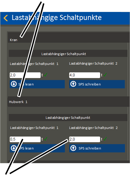
Load-controlled switching points for crane and hoist 1 |
|
|
| |
|
Load-controlled switching points 1 and 2 |
|
● The window "Load-controlled switching points" appears.
● The current settings are displayed.
Enter the load as of which the
corresponding output should be switched.
─ The load can be entered separately for the crane (total load of both hoists) and for the individual hoist(s).
─ There are up to two switching points available, which can switch at different loads.
─ Additional functions of the load-controlled switching points and the electrical connection can be found in the wiring diagram.
Click on the "Write PLC"
button.
The function of the load-controlled switching points is monitored by the PLC. Every output of each individual load-controlled switching point has an additional input for this. As soon as an output has switched, a signal must be present on the respective corresponding input. If this signal is not present, an error message is displayed. The electrical connection is done according to the specific order and is specified in the wiring diagram.