Log in as user "Abnahme"
(commissioning) (user level [2]) in KranOS. See Connecting laptop or
tablet computer with ABUControl.
Log in as user "Abnahme"
(commissioning) (user level [2]) in KranOS. See Connecting laptop or
tablet computer with ABUControl.The travel profiles of the drive axles (crane travel profile, trolley travel profile) can be adjusted to individual usage in the acceleration and braking time as well in the maximum and minimum speed.
For this work step, access from a laptop or tablet computer to KranOS is necessary. The user "Abnahme" (commissioning) (user level ‚[2]) must be logged in.
|
Overview: Navigation in KranOS |
|
User "Abnahme" (commissioning) à "Crane travel" à "Crane travel profile parameter" |
|
User "Abnahme" (commissioning) à "Trolley travel" à "Trolley travel profile parameter" |
Log in as user "Abnahme"
(commissioning) (user level [2]) in KranOS. See Connecting laptop or
tablet computer with ABUControl.
Select the desired crane axis
(e.g. crane travel) in the main menu.
● The window for the requested crane axis appears.
Click on the "Crane travel
profile parameter" (or "Trolley travel profile parameter") menu item in the
"Settings" menu (three horizontal bars).
● The "Parameter" window for the corresponding crane axis appears.
● The current values are displayed.
Set the desired values.
|
Speed |
Setting acceleration time and braking time |
|
| |
|
Part load |
|
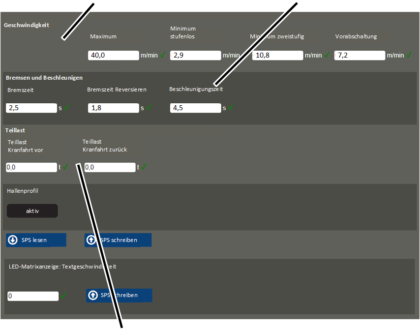
"Speed" section:
This section pertains to the maximum and minimum travel speed of the crane (or trolley) in connection with the various movement profiles.
The crane (or trolley) travels slower at a low value and faster at a high value.
The movement profiles can be selected on the "Movement profile". See Selecting movement profiles (travel profiles and hoist profiles) [1] [2]‚.
|
|
Danger due to excessively high travel speed! The crane (trolley) can become uncontrollable at excessive travel speed. Before changing the parameter, contact ABUS Service and heed legal requirements. |
─ "Maximum": Maximum crane (or trolley) travel speed.
With step-less movement profile: If the button is pressed and held in the second level, the crane (or trolley) accelerates to this maximum travel speed.
With two-step movement profile: If the button is pressed and held in the second level, the crane (or trolley) accelerates to this travel speed.
─ "Minimum step-less": This is the lowest speed at which the crane (or trolley) can travel with a step-less movement profile.
If the button is pressed and held in the first level, the crane (or trolley) accelerates to this travel speed.
─ "Minimum two-step": This is the lowest speed at which the crane (or trolley) can travel with a two-step movement profile.
If the button is pressed and held in the first level, the crane (or trolley) accelerates to this travel speed.
─ "Braking function": Travel speed at which the crane (or trolley) brakes if the travel limit switch for the braking function is activated.
"Braking and accelerating" section:
This section pertains to the braking time and the acceleration time of the crane (or trolley) in connection with the various movement profiles.
The drive brakes or accelerates faster at a low value and slower at a high value.
The movement profiles can be set on the "Movement profile" page. See Selecting movement profiles (travel profiles and hoist profiles) [1] [2]‚.
|
|
Danger due to too short braking time and acceleration time If the braking time or acceleration time is set too short, excessive load can be placed on the statics of the supporting structure (e.g. of the building) and damage it. Before changing the parameter, contact ABUS Service. |
|
|
Danger due to too long braking time If the braking time is too long, the crane (the trolley) could possibly not come to a stop in time to avoid colliding with other cranes (trolleys). After changing the parameter, test the braking time. |
─ "Braking time": Time in which the drive brakes from the travel speed.
The entered time always refers to the complete braking from the maximum travel speed according to the type plate until a standstill is reached.
With this value, the drive brakes when the key is released from the first or second level.
─ "Braking time - reverse": Time in which the drive brakes from the travel speed for reversing.
The entered time always refers to the complete braking from the maximum travel speed according to the type plate until a standstill is reached.
With this value, the drive brakes when the key is released from the first or second level and the key for the opposite direction is directly pressed and held.
─ "Acceleration time": Time in which the drive accelerates to the travel speed.
The entered time always refers to the complete acceleration from a standstill until the maximum travel speed according to the type plate is reached.
With this value, the drive accelerates from a standstill when the key is pressed in the first level, or if the key is pressed and held in the second level.
Additional sections:
─ Only with crane travel profile: "Part load crane travel ahead" and "Part load crane travel back": Load as of which the load-dependent crane distancing system is to be switched on. See Displaying the status of the crane axes [1] [2]. The load can be separately set for both travel directions.
With a general (load independent) crane distancing system, the value that is entered here is irrelevant.
─ "Building profile": This displays whether a building profile is available for the crane.
─ "LED matrix display: text speed": Speed with which the scrolling text runs through the LED matrix display. For a lower value, the scrolling text runs faster; for a higher value it runs more slowly.
The set text speed is saved directly in the LED matrix display and not in the PLC. For this reason, the "Write PLC" button next to the input field must be clicked separately. Also, the current value which is saved in the LED matrix display is not displayed here.
─ "Rotation direction" for –B76 and –B77 (for crane travel) or –B56 and –B57 (for trolley travel): Rotation direction for both cross-type limit switches that are used for the building profile control. The numbers from 0 to 5 indicate the switching statuses of the cross-type limit switch. They can be read at a small arrow on the cross-type limit switch.
If the cross-type limit switch is installed correctly (installed according to layout plan, housing below, switching cross above) it interconnects the switching statuses in descending order by (5-4-3-2-1-0), if the crane travels forwards or the trolley travels to the right.
If the cross-type limit switch is installed upside down (installed according to layout plan, housing above, switching cross below) it interconnects the switching statuses in ascending order by (0-1-2-3-4-5), if the crane travels forwards or the trolley travels to the right.