Overview: Terminating resistor in the CAN bus
network
In a CAN bus network such as at ABUControl, a central CAN bus
line runs as the backbone. On both ends of the backbone of the CAN bus line the
terminating resistors must be set. This means that disruptions in the CAN bus
line can be prevented. Further CAN bus devices of the CAN bus network can be
connected on this backbone in a radial manner without terminating resistor to a
CAN distributor.
Depending on the crane, the CAN bus network can vary greatly.
For example, the position of the LED matrix display must be taken into account,
as well as the number of trolleys and the type (twin hoist with two hoist drives
per trolley), among other considerations.
This section describes both of the two basic CAN bus networks
for cranes with one and with two trolleys. For all other CAN bus networks,
contact ABUS Service.
When replacing CAN bus devices:
If faulty CAN bus devices are exchanged (e.g. PLC, CAN
distributor, LED matrix displays, etc.), the terminating resistor on the new CAN
bus device must be switched the same as it was on the faulty CAN bus device.
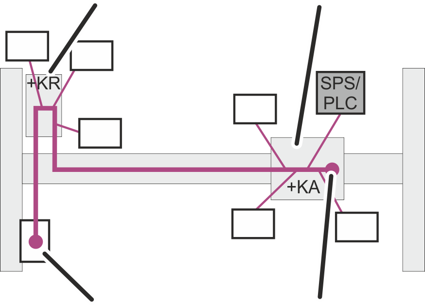
Only for cranes with one
trolley
|
CAN distributor in the crane panel with switched-off
terminating resistor |
CAN
distributor in the trolley with terminating resistor |
|
|
|
LED matrix display on the backbone with terminating
resistor |
Terminating resistor |
In the CAN bus network of ABUControl for a crane with one
trolley, the backbone runs from the hoist panel (+KA) through the crane panel
(+KR) to the LED matrix display.
The terminating resistors are switched on in the CAN distributor in the hoist
panel (+KA) and in the LED matrix display. The terminating resistor in the CAN
distributor in the crane panel (+KR) is switched off.
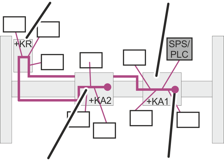
Only for cranes with two
trolleys
|
CAN
distributor terminating resistor "off" |
CAN
distributor in Trolley 1 |
|
|
|
CAN
distributor in Trolley 2 |
Terminating
resistor "on" |
In the CAN bus network of ABUControl for a crane with two
trolleys, the backbone runs from hoist panel 1 (+KA1) through the crane panel
(+KR) to hoist panel 2 (+KA2).
The terminating resistors are switched on in the CAN
distributors in the two hoist panels 1 + 2 (+KA 1 und +KA2). The terminating
resistor in the CAN distributor in the crane panel (+KR) is switched off.