Log in as user "Abnahme"
(commissioning) (user level [2]) in KranOS. See Connecting laptop or
tablet computer with ABUControl.
Log in as user "Abnahme"
(commissioning) (user level [2]) in KranOS. See Connecting laptop or
tablet computer with ABUControl.The load measuring system continuously determines the current load on the load hook. This value is necessary for many crane functions, especially for the overload protection.
The load measuring system must be calibrated once with an increased test load in order for the attached load to be evaluated.
For this work step, access from a laptop or tablet computer to KranOS is necessary. The user "Abnahme" (commissioning) (user level ‚[2]) must be logged in.
Requirements for the calibration:
─ A test load is necessary for the calibration.
─ The dimensions of the test load must be known exactly.
─ The dimensions of the test load should if possible correspond to the maximum load capacity of the crane or the trolley, or it should lie as close as possible to the maximum load capacity of the crane or the trolley.
For the dynamic test of the maximum load capacity of the crane a test load of 110% of the maximum load capacity of the crane is usually used. In general, this can also be used for the calibration.
A load above the maximum load capacity of the crane may only be lifted by a qualified person for the test before the first commissioning of crane installations.
ABUControl blocks the lifting function for loads over 110% of the maximum load capacity of the crane. The load can no longer be lifted and can only be set down instead.
|
Overview: Navigation in KranOS |
|
User "Abnahme" (commissioning) à "Hoist" à "Hoist calibration" |
Log in as user "Abnahme"
(commissioning) (user level [2]) in KranOS. See Connecting laptop or
tablet computer with ABUControl.
Select the desired hoist (e.g.
Hoist 1) in the main menu.
● The window for the requested hoist appears.
Click on the "Hoist calibration"
menu item in the "Settings" menu (three horizontal bars).
The area in the left of the "Hoist calibration" window is used for the calibration with an increased test load. Whereas the "Calibrating load sensor" button is only needed if the fixed point crosshead or the load sensor was replaced.
|
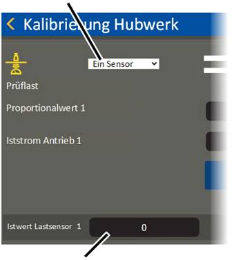
"Sensor" selection field |
| |
|
| ||
|
"Load sensor actual value" field |
| |
● The "Hoist calibration" window appears.
Select the value "One sensor" in
the "Sensor" selection field.
The load on all wire rope hoists is measured with ONE sensor.
The value "Two sensors" is only required in exceptional cases for certain version of the GM modular.
● The currently measured value is displayed and constantly updated in the "Load sensor actual value" field.
The current values in the "Proportional value" and "Load sensor actual value" lines are measured values without measurement units, which are later used to calculate the load.
If necessary: Take the load and
lifting tackle out of the load hook.
Lift/lower the empty load hook
so that it hangs relatively far up, e.g. about a metre under the highest hook
position.
This ensures the weight of the unwound wire rope is not included in the measurement.
|
|
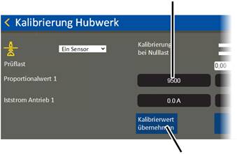
Measured proportional value |
|
| |
|
|
"Accept calibration value" button |
● Click on the "Accept calibration value" button in the "Calibration at zero load" column.
● The current value is saved as the "zero load" and displayed in the "Proportional value" field in the column "Calibration at zero load".
|
|
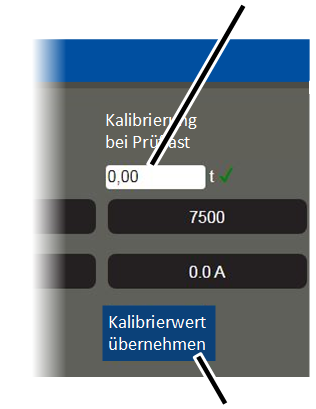
"Test load" input field |
|
| |
|
|
"Accept calibration value" button |
Click on the "Test load" input
field in the "Calibration at test load" column.
Input the test load
dimensions.
● The input value is accepted.
Observe the applicable
occupational health and safety regulations and lift the test load.
Wait until the test load hangs
calmly in the load hook.
Click on the "Accept calibration
value" button in the "Calibration at test load" column.
● The current value is saved as the test load and displayed in the "Proportional value" field in the column "Calibration at test load".