Installing, setting and teaching-in distance
sensor [2]
With trolley travel distance sensors: The trolleys measure
their distance from the end of the main girder in each case with a distance
sensor laser beam. With this measurement, the braking function and shut-down can
be implemented (instead of by the usual cross-type limit switch) and also the
anti-collision device (instead of by the usual reflective light barriers)
through the resulting calculated position of both trolleys. In the joint
operation of both trolleys, the constant distance between the trolleys is also
calculated and correspondingly controlled.
With crane travel distance sensor: The cranes measure their
distance from another crane on the same run (or from both of the other cranes on
the same run) via the distance sensor laser beam. This enables the braking
function and the shut-down to the other crane/s on the same run to be
implemented (instead of by the usual reflective light barriers). This also
enables the constant distance to be controlled in tandem operation. The braking
function and shut-down at the end of the crane track is implemented via the
cross-type limit switch.
Reflective light barriers or one-way light barriers are
generally used when there is a crane distancing system due to structural reasons
or a load-dependent crane distancing system. Cross-type limit switches are
generally used for building profile controls.
For this work step, access from a laptop or tablet computer
to KranOS is necessary. The user "Abnahme" (commissioning) (user level ‚[2])
must be logged in.
|

|
Danger due to malfunction
The distance sensor can only fulfil its safety
function when it is correctly fastened. Otherwise malfunctions could occur
(e.g. if the distance sensor is not correctly attached and falls down).
Carefully fasten and align the distance sensor and
reflector. |
Overview:
Distance sensor and reflector
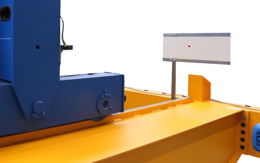
─ With
crane travel distance sensor: The distance sensor of the crane and the reflector
for the distance sensor of another crane on the same run are fastened on a
shared mount on the end carriage. On the other crane on the same run, the
placement of distance sensor and reflector are accordingly interchanged. The
light beams of the distance sensors are not allowed to cross each other.
─ With
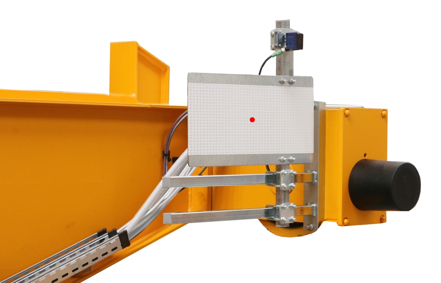
trolley travel distance sensor on the wire rope hoist GM modular: The distance
sensor is pushed laterally onto a mount in the cover of the cable drum. The
reflector is taped onto the end carriage of the crane as adhesive foil or
fastened on a square tube.
─ With
trolley travel distance sensor on the wire rope hoist GM compact: The distance
sensor is installed on the trolley frame with a magnetic mount. The reflector is
taped onto the end carriage of the crane as adhesive foil or fastened on a
square tube.
Installing
distance sensor
The distance sensor is either fastened with a mount on a
square tube on the end carriage or attached to the wire rope hoist with a
magnetic mount.
Only with distance
sensor on square tube
Installing the
mount for the light barriers
|
Threaded bracket |
|
|
|
|
Mount |
Pipe
clamp |
|
|
|
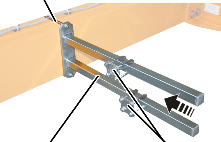
 Attach the mount on the end
carriage.
 Bolt the mount onto the threaded
bracket.
|
Threaded bracket |
Tightening torque |
|
M8 |
25 Nm |
|
M10 |
50 Nm |
|
M12 |
75 Nm |
 Slide on the two pipe clamps and
secure them.
 Push the square tube in the pipe
clamps and screw tight.
|
Adapter |
Mounting
plate |
|
|
|
Distance
sensor |
|
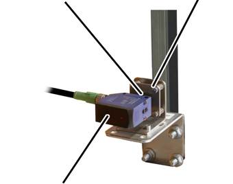
 Push the entire mount onto the
square tube.
 Screw in the mount using M8 rib
nuts (4x) and tighten by hand.
 Push the distance sensor into
the adapter on the mounting plate and tighten the screws.
Only with distance
sensor on magnetic mount
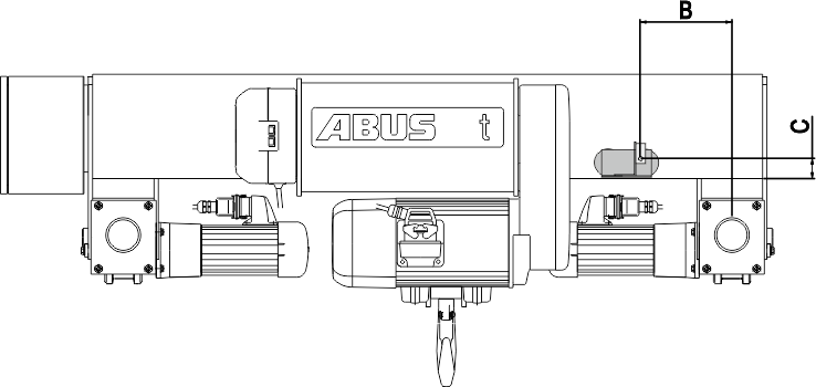
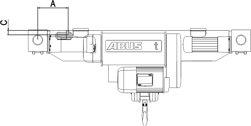
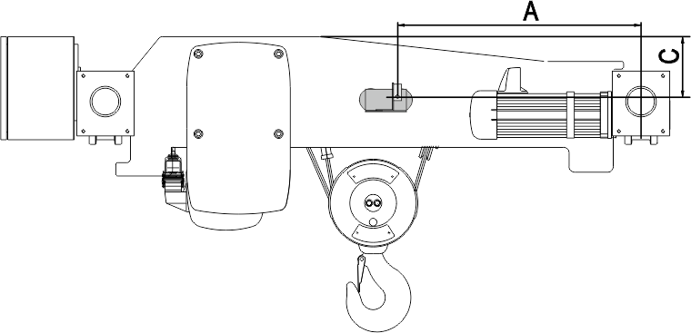
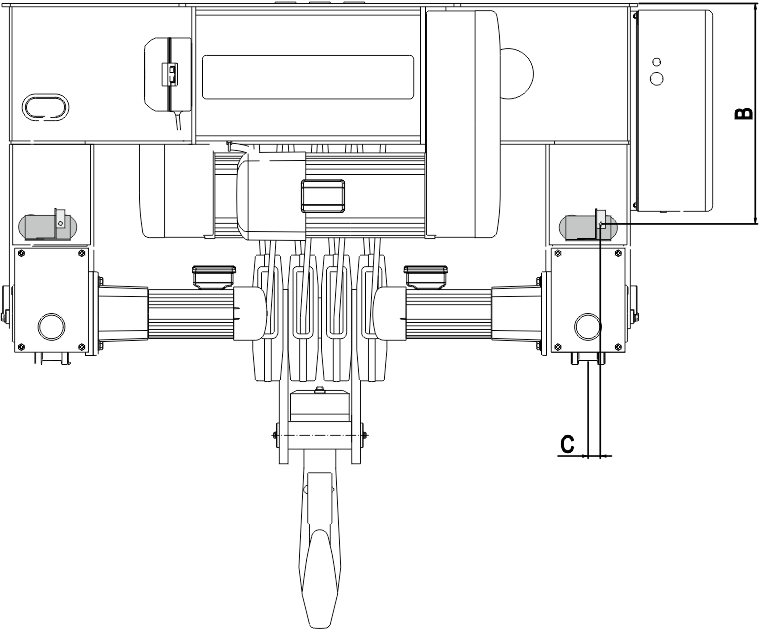
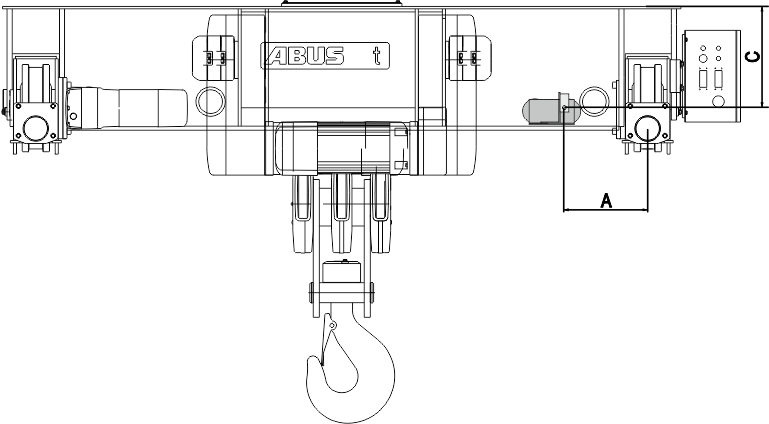
 Select the appropriate size and
type from the following drawing.
 Read the dimensions A and B from
the following table.
|
|
Magnetic
mount |
|
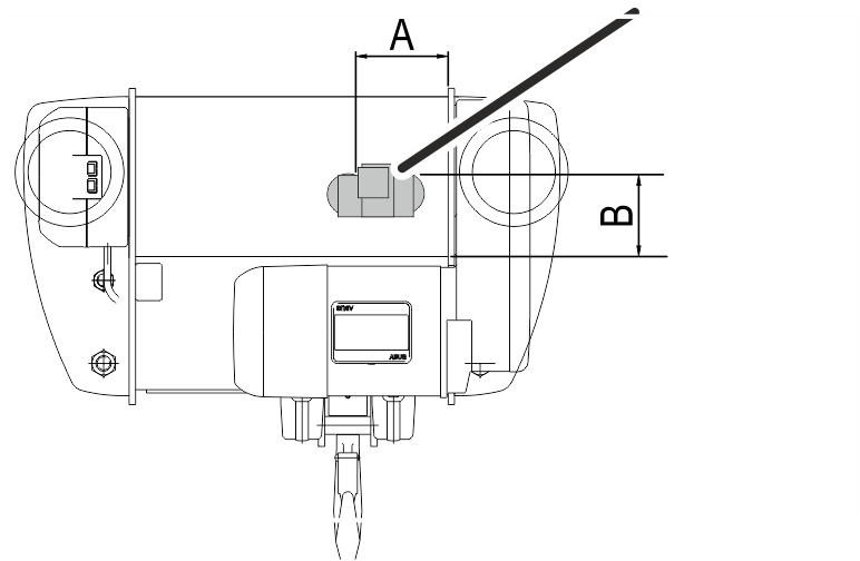
|
Assembly position of the magnetic mount on wire rope
hoist E
|
Size |
Dimension A |
Dimension B |
|
800 4/1 |
130 |
100 |
|
1000 2/1 |
130 |
130 |
|
1000 4/1 |
130 |
130 |
|
2000 2/1 |
130 |
130 |
|
2000 4/1 |
130 |
160 |
|
3000 2/1 |
130 |
160 |
|
3000 4/1 |
130 |
160 |
|
5000 2/1 |
130 |
160 |
|
5000 4/1 |
130 |
200 |
|
6000 2/1 |
130 |
160 |
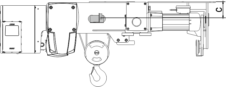
Assembly position of the magnetic mount on wire rope
hoist S. Observe dimension C and fasten the distance sensor as centred as
possible on the rope drive.
|
Size |
Dimension A |
|
800 4/1 |
140 |
|
1000 4/1 |
180 |
|
2000 4/1 |
180 |
|
3000 2/1 |
180 |
|
3000 4/1 |
245 |
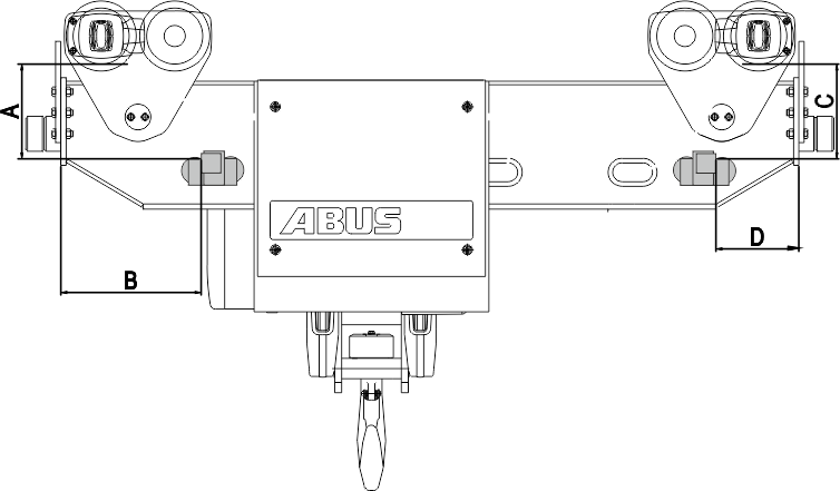
Assembly position of the magnetic mount on wire rope
hoist U. Observe the different positions for the left and right distance
sensor.
|
Size |
Dimension A |
Dimension B |
Dimension C |
Dimension D |
|
5000 4/1 |
330 |
350 |
310 |
660 |
|
6000 2/1 |
325 |
640 |
285 |
560 |
|
6000 4/1 |
400 |
320 |
370 |
595 |
|
7000 2/1 |
360 |
420 |
450 |
550 |
Assembly position of the magnetic mount on wire rope
hoist D.
|
Size |
Dimension A |
Dimension B |
|
800 4/1 |
210 |
60 |
|
1000 4/1 |
200 |
50 |
|
2000 2/1 |
200 |
50 |
|
2000 4/1 |
200 |
50 |
|
3000 2/1 |
225 |
50 |
|
3000 4/1 |
225 |
50 |
|
5000 2/1 |
200 |
50 |
|
5000 4/1 |
130 |
50 |
|
5000 4/2 |
200 |
50 |
|
5000 6/1 |
130 |
50 |
|
6000 2/1 |
200 |
45 |
|
6000 4/1 |
170 |
50 |
|
6000 6/1 |
200 |
50 |
|
7000 2/1 |
190 |
50 |
|
7000 4/1 |
190 |
50 |
|
7000 4/2 |
190 |
50 |
|
7000 6/1 |
190 |
60 |
|
7000 8/2 |
190 |
50 |
Assembly position of the magnetic mount on wire rope
hoist DA.
|
Size |
Dimension A |
Dimension C |
|
800 4/1 |
540 |
30 |
|
1000 4/1 |
250 |
35 |
|
2000 2/1 |
520 |
55 |
|
2000 4/1 |
520 |
55 |
|
3000 2/1 |
470 |
50 |
|
3000 4/1 |
550 |
60 |
|
5000 2/1 |
550 |
45 |
|
5000 4/1 |
610 |
55 |
|
6000 2/1 |
565 |
50 |
|
6000 4/1 |
700 |
55 |
|
7000 2/1 |
590 |
70 |
|
7000 4/1 |
390 |
170 |
|
7000 6/1 |
350 |
200 |
Assembly position of the magnetic mount on wire rope
hoist DQA. Observe dimension C and fasten the distance sensor as centred as
possible on the rope drive.
|
Size |
Track |
Dimension C |
|
2000 |
1400 |
100 |
|
3000 |
1400 |
85 |
|
2000 |
1600 |
100 |
|
3000 |
1600 |
85 |
|
5000 |
1600 |
75 |
|
6000 |
1600 |
80 |
|
2000 |
2000 |
95 |
|
3000 |
2000 |
85 |
|
5000 |
2000 |
75 |
|
6000 |
2000 |
85 |
|
2000 |
2500 |
100 |
|
3000 |
2500 |
80 |
|
5000 |
2500 |
75 |
|
6000 |
2500 |
85 |
|
7000 |
2500 |
100 |
|
7000 |
3000 |
100 |
|
7000 |
3500 |
100 |
Assembly position of the magnetic mount on wire rope
hoist Z.
|
Size |
Dimension B |
|
5000 4/2 |
535 |
|
5000 8/2 |
580 |
|
6000 4/2 |
565 |
|
6000 8/2 |
570 |
|
7000 4/2 |
725 |
|
7000 6/2 |
850 |
|
7000 8/2 |
660 |
|
7000 10/2 |
300 |
|
7000 12/2 |
470 |
Assembly position of the magnetic mount on wire rope
hoist ZA.
|
Size |
Dimension A |
Dimension C |
|
5000 8/2 |
315 |
355 |
|
6000 8/2 |
315 |
200 |
|
7000 6/2 |
440 |
500 |
|
7000 8/2 |
420 |
482 |
|
7000 10/2 |
500 |
570 |
|
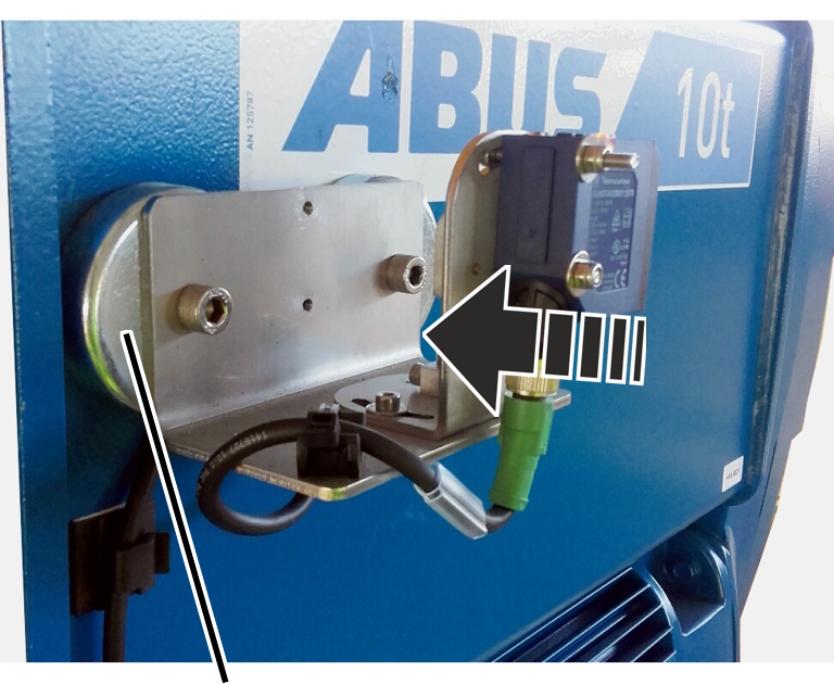
|
|
Magnetic
mount |
|
 Attach the magnetic mount to the
wire rope hoist.
The position specified refers to the point on the distance
sensor at which the laser beam emerges from it.
Depending on the installation situation, the position for the
magnetic mount may already be marked.
Only with wire rope
hoist GM modular
|
Drum
side |
|
|
|
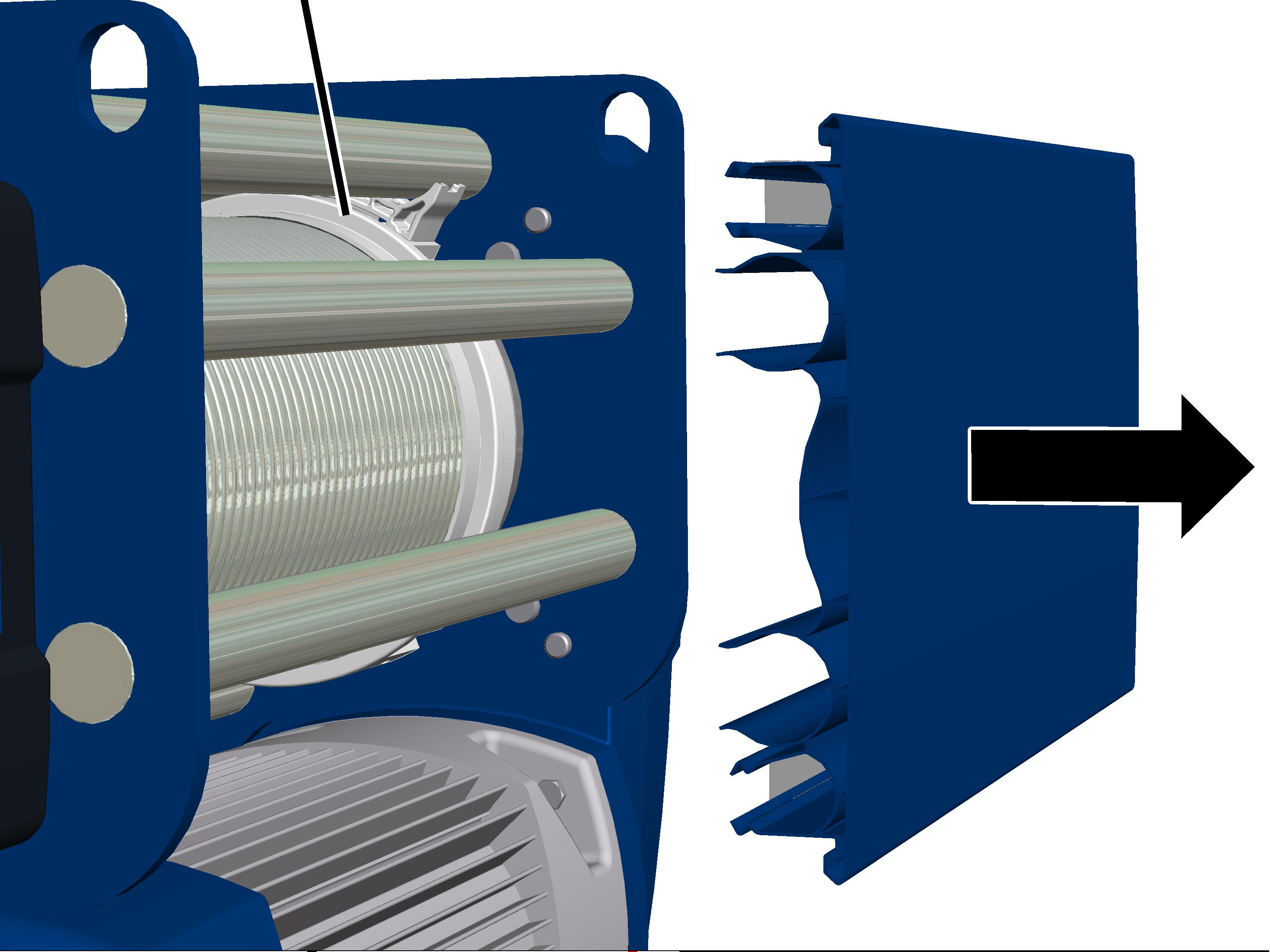
 Pull off the cover from the drum
side.
|
|
Mount |
|
|
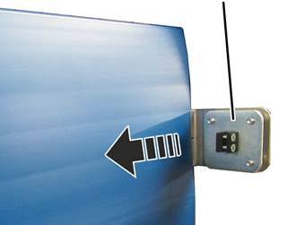
 Push the mount with the slit
laterally into the cover.
 Place the cover on the wire rope
hoist.
 Push the distance sensor into
the adapter on the mounting plate and tighten the screws.
Installing
reflector
 During tandem control: Put the
cranes at maximum distance.
 During the joint operation of
two trolleys: Put trolleys at maximum distance.
Only with reflector
as adhesive foil
 Move the adhesive foil so that
the laser point is as close to centred as possible.
The more precise adjustment is done later on the distance
sensor. The position of the adhered adhesive foil can no longer be
corrected.
 Press on the adhesive foil.
Only with reflectors
on a square tube
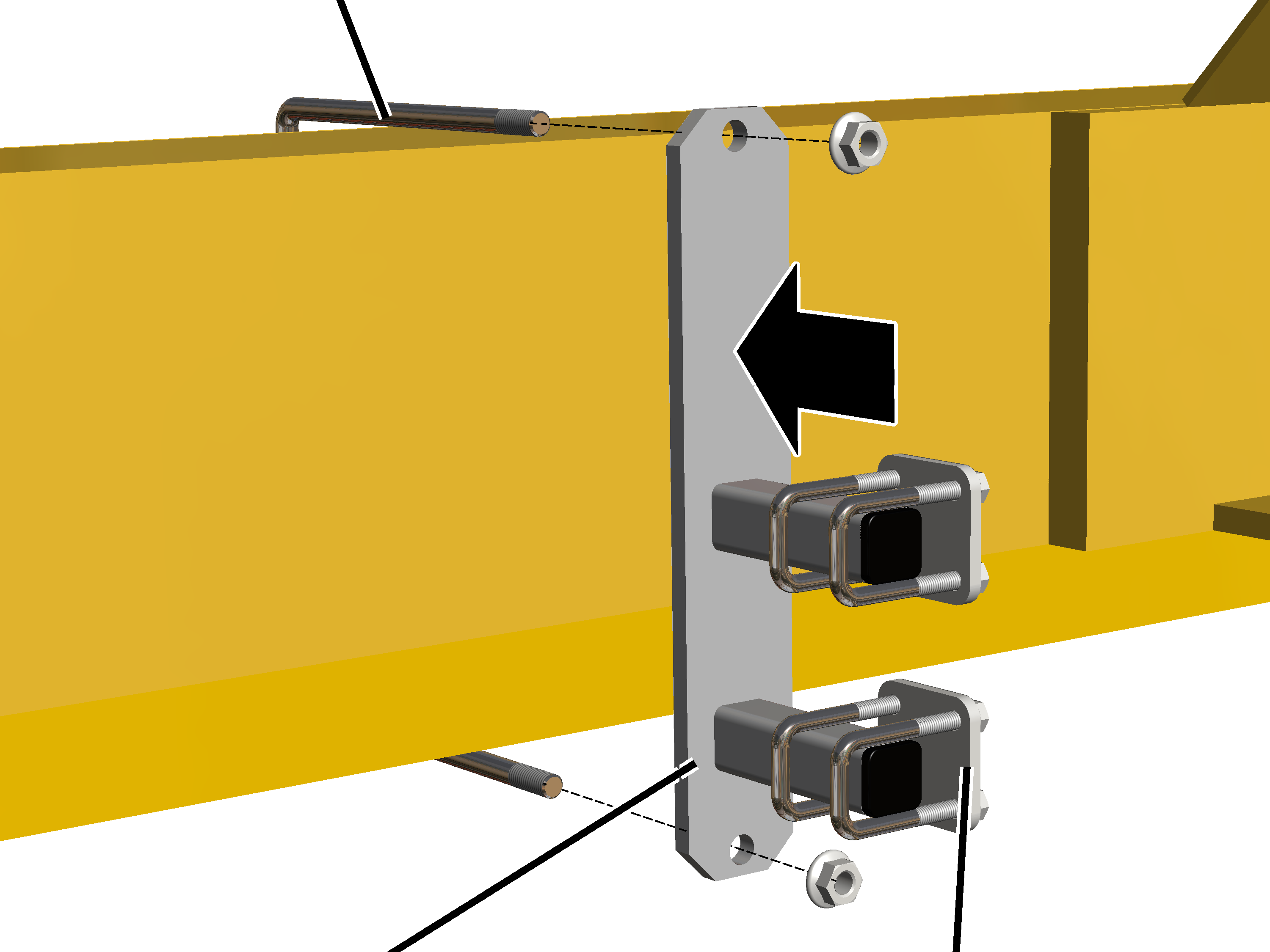
|
Threaded
bracket |
|
|
|
|
Mount |
Pipe
clamp |
 Bolt the mount onto the threaded
bracket.
|
Threaded bracket |
Tightening torque |
|
M8 |
25 Nm |
|
M10 |
50 Nm |
|
M12 |
75 Nm |
 Slide on the two pipe clamps and
secure them.
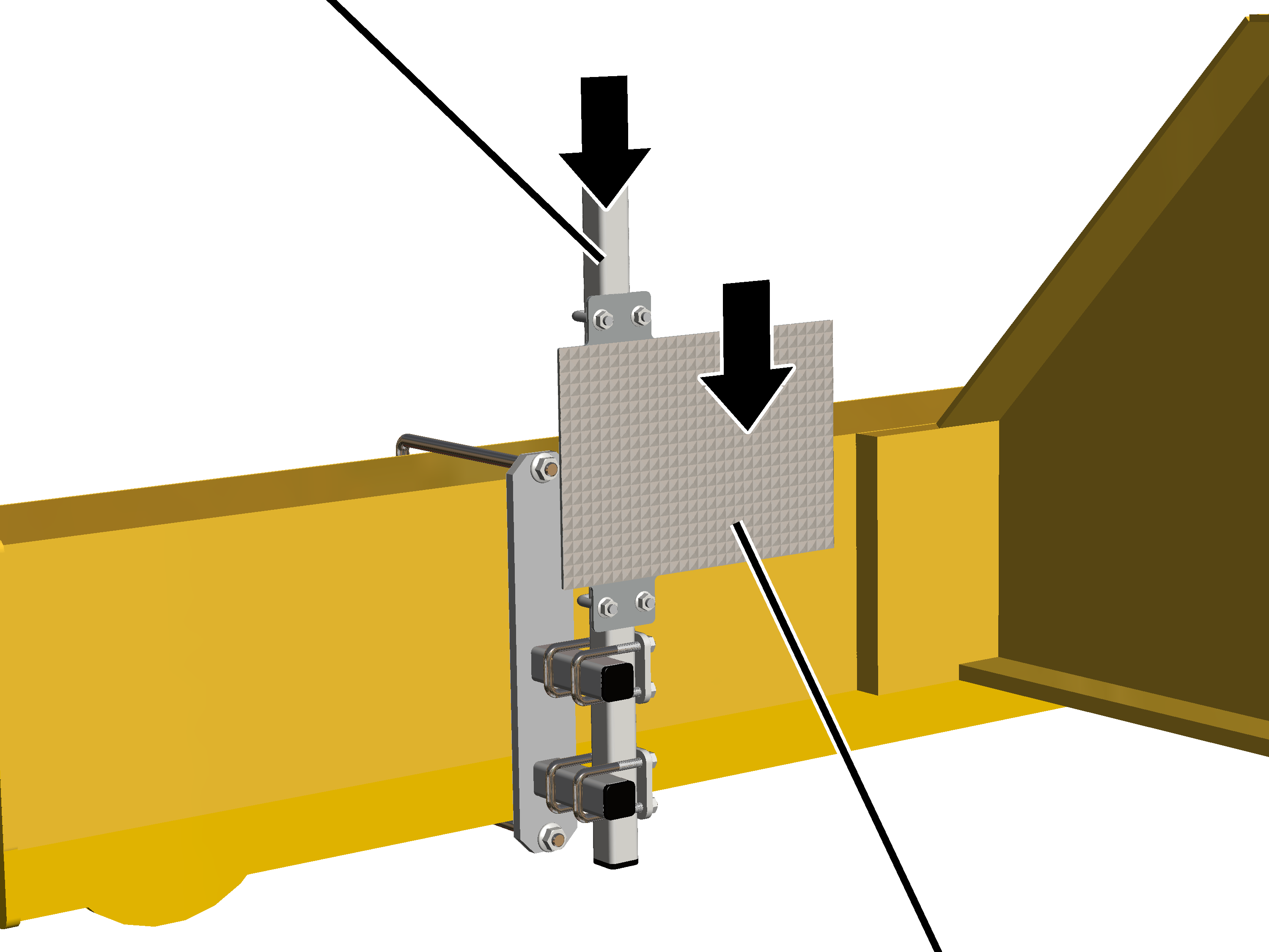
|
Square
tube |
|
|
|
|
|
Reflector |
 Push the square tube in the pipe
clamps.
 Push the reflector onto the
square tube.
 Move the reflector so that the
laser point is as close to centred as possible.
The more precise adjustment is done later on the distance
sensor.
 Screw on the pipe clamps and
reflector using M8 rib nuts (4x) and tighten by hand.
Setting distance
sensor
Only with mount
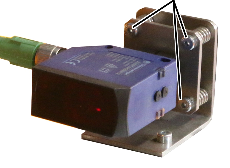
|
|
Fillister-head screw M6x20 |
|
|
 Adjust the distance sensor with
M6x20 fillister-head screws (3x) so that the laser point is exactly on the
centre of the reflector.
● If the
distance sensor receives the laser beam reflected from the reflector, the LEDs
on the distance sensor light up.
● If the
distance sensor does not receive the laser beam, one of the LEDs flashes.
Only with magnetic
mount
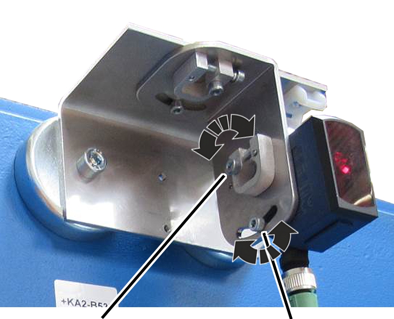
Adjust the distance sensor with the rough and fine adjustment
screws so that the laser point is exactly in the centre of the reflector.
|
|
|
Fillister-head screw for the fine adjustment |
Fillister-head screw for the rough
adjustment |
 Release the fillister-head screw
in the elongated hole for the rough adjustment and tilt the distance sensor.
 If necessary, release the
fillister-head screw for the fine adjustment and fine-adjust the distance sensor
with the short, crosswise-lying fillister-head screw.
● If the
distance sensor receives the laser beam reflected from the reflector, the LEDs
on the distance sensor light up.
● If the
distance sensor does not receive the laser beam, one of the LEDs flashes.
 Tighten the long fillister-head
screws (2x).
 Travel along the entire
traversing range with the crane (or the trolley) and examine whether the laser
beam meets the reflector at every position and does not drift sideways or
upwards/downwards.
Opening the
distance sensor settings
|
Overview: Navigation in KranOS |
|
User "Abnahme" (commissioning) à "Crane travel" à "Crane travel distance
sensors" |
|
User "Abnahme" (commissioning) à "Trolley travel" à "Trolley travel distance
sensors" |
 Log in as user "Abnahme"
(commissioning) (user level [2]) in KranOS. See Connecting laptop or
tablet computer with ABUControl.
 Select the desired trolley drive
or crane travel drive (e.g. trolley travel 1 or crane travel) in the main
menu.
● The window
for the requested drive appears.
 Click on the "Crane travel
distance sensors" (or "Trolley travel distance sensors") menu item in the
"Settings" menu (gear wheel on a yellow background).
Teaching-in
distance sensor
Now the distance sensor will be taught in. For this purpose,
the crane/trolley is travelled to the desired position and the distance sensor
value determined for this position is saved in ABUControl.
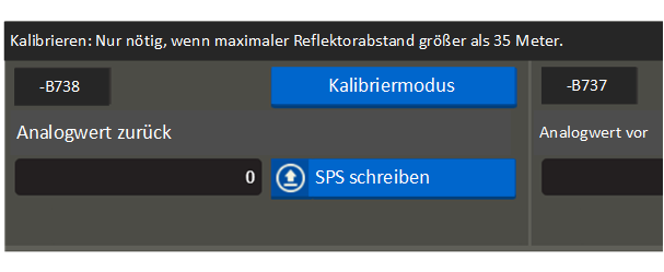
Note regarding "Calibration mode"
The upper area of the window "Crane travel distance sensors"
or "Trolley travel distance sensors" is used to calibrate the distance sensor
when the maximum distance to the reflector is greater than 35 metres. This is
only necessary in rare cases. In addition, this area of KranOS is only intended
for future versions of KranOS and is currently without any assigned
functions.
|
Description field with current position |
"Teach-in mode" button |
|
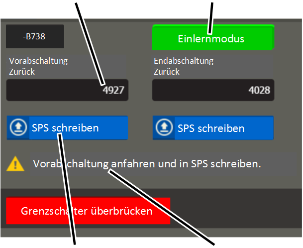
|
|
"Write
PLC" button |
Message
with the next switching point to be travelled to |
 Click on "Teach-in mode"
button.
● The
button's background turns green.
● "Teach-in
mode" is switched on.
● The "Bridge
limit switch" button turns red.
It is possible that switching points for braking function and
shut-down already saved will now be ignored.
Thus, the trolley (the crane) can be moved to any new
positions.
● A message
appears for which switching point (braking function or shut-down) is to be
travelled to.
 Travel the trolley (the crane)
to the corresponding position.
The distance sensor must be at least 0.5 m away from the
reflector.
 In the column for the switching
point which is to be learnt: Click on the "Write PLC" button.
● The
measured value for the current position is displayed in the description
field.
The displayed value is a measured value without measurement
unit, which is used to calculate the position later.
 Repeat the process for all
further switching points.
After the switching points have been saved:
● The
teach-in mode ends automatically.
● The limit
switch bridging turns off automatically.

