For a load-dependent crane distancing system, it must be known in both controls (in the crane and the other crane on the same run) whether the set load has fallen below or been exceeded on the other crane. This information is transmitted between the cranes via a light barrier. Each crane has light barriers for signal transmission; one as a transmitter and one as a receiver.
|
|
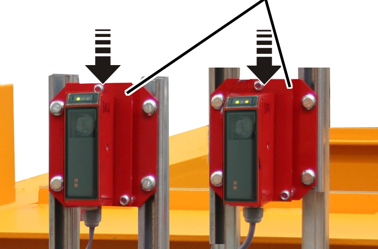
─ The light barriers for transmitting the release signal are installed on opposite ends of the end carriages of the cranes.
─ One transmitter and one receiver is installed on each crane.
─ The transmitter is installed above and the receiver below on a crane. It is the other way around on the other crane.
|
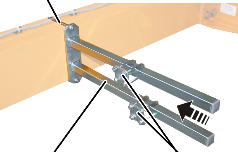
Threaded bracket |
| |
|
| ||
|
Mount |
Pipe clamp | |
 Attach the mount to opposite
ends of the end carriages.
Attach the mount to opposite
ends of the end carriages.
Bolt the mount onto the threaded bracket.
|
Threaded bracket |
Tightening torque |
|
M8 |
25 Nm |
|
M10 |
50 Nm |
|
M12 |
75 Nm |
Slide on the two pipe clamps and
secure them.
|
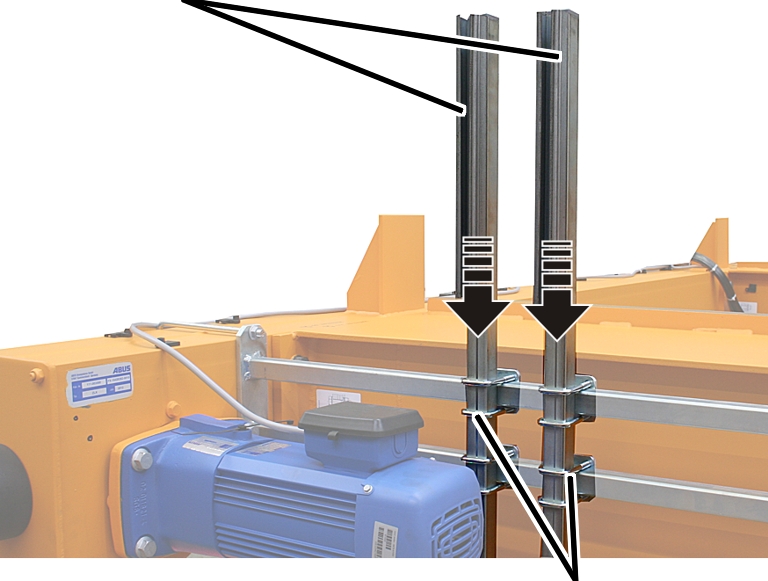
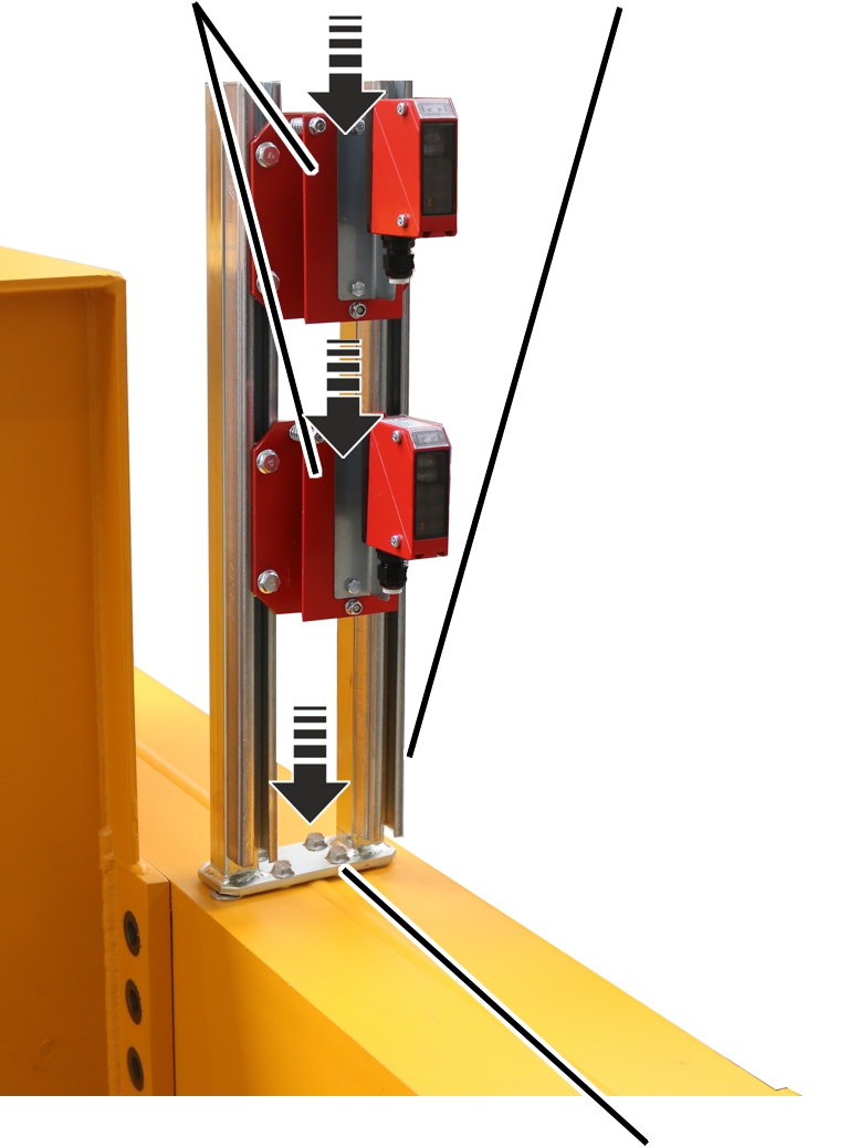
Mount for the light barriers |
|
|
| |
|
|
Pipe clamps |
Push the mount for the light
barriers (2x) into the pipe clamps.
Align the mounts and
hand-tighten the pipe clamps.
|
|
Light barriers |
|
| |
Push light barriers into the
mounts.
Screw the light barriers until
hand-tight.
Route the light barrier
connection cables to the crane panel and secure with cable clips.
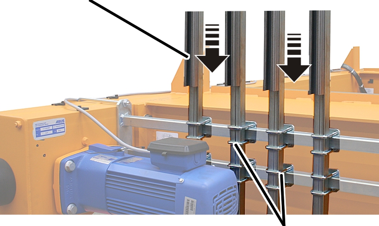
If there is little space due to the lower installation height of the crane over the main girder, the light barriers can be installed side-by-side with additional mounts rather than above one another.
|
Mount for the light barriers |
|
|
| |
|
|
Pipe clamps |
 Push the mount for the light
barriers (4x) into the pipe clamps.
Push the mount for the light
barriers (4x) into the pipe clamps.
Align the mounts and
hand-tighten the pipe clamps.
|
|
Light barriers |
|
| |
Push light barriers into the
mounts.
Screw the light barriers until
hand-tight.
Route the light barrier
connection cables to the crane panel and secure with cable clips.
|
Light barriers |
Mount for the light barriers |
|
| |
|
|
Rib screws M8x20 |
Place the mount for the light
barriers on the holes on the end carriage.
Screw in the mount for the light
barriers with the M8x20 rib screws.
Push light barriers into the
mounts.
Screw the light barriers until
hand-tight.
Route the light barrier
connection cables to the crane panel and secure with cable clips.
|
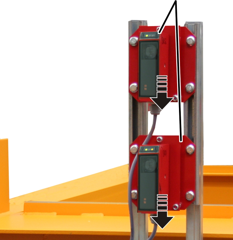
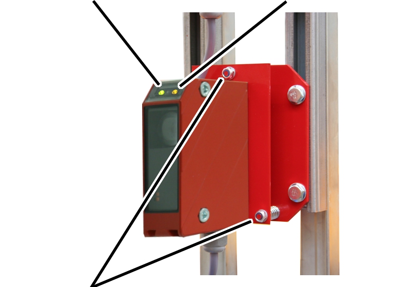
Green LED: operating voltage |
Yellow LED (only on the receiver): visual contact to the transmitter exists |
|
| |
|
Self-locking nuts for alignment |
|
Align both light barriers on the
crane and the other crane on the same run exactly to one another with the
self-locking nuts. The yellow LED must light up on the receiver.
─ Green LED (on transmitter and receiver): operating voltage present.
─ Yellow LED (only on the receiver): visual contact to the transmitter exists.
As soon as the crane can be
traversed: Run the entire crane track in various distances with the crane and
the other crane on the same run and check whether the alignment of the light
barriers are correct (the yellow LED on the receiver (visual contact exists)
must light up in the entire traversing range). If necessary, realign the light
barriers.
Due to deviations in the position of the crane track, the alignment of the light barriers can differ from each other.